Continue to Site

Welcome to our site!

Electro Tech is an online community (with over 170,000 members) who enjoy talking about and building electronic circuits, projects and gadgets. To participate you need to register. Registration is free. Click here to register now.

  • Welcome to our site! Electro Tech is an online community (with over 170,000 members) who enjoy talking about and building electronic circuits, projects and gadgets. To participate you need to register. Registration is free. Click here to register now.

Relay Chatter

Status
Not open for further replies.
hi Andrew,
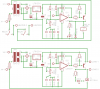
If the new thermistor is 5Kish and the old one was 10Kish I would change the R1 resistor from 10K down to 4K7.
This should allow the mid range and tempr pots to work as they did on the original circuit.

OK.?
Hope you enjoyed the Kruger Park trip, I'll not be going to SA untill Nov09 this year.:(
 
Last edited:
Hi Eric,

thanks for that. Gonna do it right away.

The Kruger had just experienced plenty rain the week before we got there. That is never good for game viewing as animals no longer need to traverse to get water as it is so abundently available in pools scattered throughout the bush. We spent the time relaxing and birding (which we both love).

Cheers
Andrew

PS: Are you down on the coast in November?
 
Hi Eric,

sounds like a great time will be had by all.

Substituted the 10k with a 4k7 .... circuit will not switch on no matter what permutation of the wiper position on the pots.

Removed the 4k7 and resoldered the 10k in place .... circuit works.

Any thoughts

Andrew
 
Hi Eric,

sounds like a great time will be had by all.

Substituted the 10k with a 4k7 .... circuit will not switch on no matter what permutation of the wiper position on the pots.

Removed the 4k7 and resoldered the 10k in place .... circuit works.

Any thoughts

Andrew
hi,
That suggests the original thermistor must be different from the 10K therm that the original design required.???

Do you have any 'hot', 'cold' resistance values for the new thermistor.

That is, can you measure the resistance when hot/cold, lets see the change.
 
Hi Eric,

From what I understand most thermistors are quoted at 25°C. The original is 10k @ 25°C. I happened to have one laying about which is about 5k @ ~25°C. The circuit from what I can understand in the write up was intended for operation at 20 - 25°C, hence the thermistor value will be at near and around its 25°C resistance of 10k.

The surplus themistor that I used needs to control the fridge at 3°C. At this temperature the cold resistance is ~ 12k. This to my mind meant both thermistors were both in about the same resistance range when at the point of triggering?

Hell this stuff confused me!

Cheers
Andrew

hi,
I see, you are using it as 'lower' tempr detector.! That means the resistance increases as the tempr falls.

I know its a bit hit and miss, [ the 741 is a poor OPA] but increase R1 to say about 15K, lets know what you get. It will not cause any damage to the 741.
 
Hi,

Could someone please cast a critical eye over the attached, specifically;

a) I have added a standard 5mm Green LED and a 330R resistor at the relay as an indicator when the relay turns on. That's 30mA, too much?
b) I think I am breaking serious design protocol by mixing 220V and 12V on the PCB. All the thinner tracks are at ~12V whilst the thicker tracks are 220V.

Regards
Andrew
 

Attachments

  • Final Board.png
    Final Board.png
    18.6 KB · Views: 165
  • Final Schematic.png
    Final Schematic.png
    14.9 KB · Views: 161
Hi,

Could someone please cast a critical eye over the attached, specifically;

a) I have added a standard 5mm Green LED and a 330R resistor at the relay as an indicator when the relay turns on. That's 30mA, too much?
b) I think I am breaking serious design protocol by mixing 220V and 12V on the PCB. All the thinner tracks are at ~12V whilst the thicker tracks are 220V.

Regards
Andrew

hi Andrew,
A bog standard led should be 10mA thru 20mA max.

Ensure a wide gap spacing on the wider tracks to any other track.
What current are the 220V tracks carrying.?
Whats the board material.?
 
Your LED is upside-down. Look at its datasheet to see if it will burn up with 30mA or if it will be very hot and very bright.

The transistor probably will not turn off because the output high voltage of the lousy old 741 opamp is not high enough. Reduce the value of R3 to 2.7k to fix it.
 
Thanks guys,

Eric and Audioguru,

- I connected the LED one way and drew it the opposite. The LED works, for how long not too sure but will buy LED's of known parameters and will alter the LED resistor to suit. The one I used happened to be laying around.

- Current of 0.82A on a 180W element cold.

- Board will be a standard epoxy glass cloth based board, don't know the copper thickness, someone will make them for me.

- The circuit does work as shown, bar for the error on the LED, but will alter R3 for safety sake.

- Was reading another post today which spoke of much better options on opamps other than the old LM741. In my junkbox I have unused TL072, TL082, TL071, LM386, LM311, LM358. Could any of these be a direct replacement? Would I be better off upgrading now and altering the circuit, would need help though.

Thanks again
Andrew
 
Last edited:
The TL072 and TL082 are pretty old FET input dual opamps with a much higher max frequency than the old 741 and almost no input current. They are also low noise. their max output high voltage is almost the same as the 741 opamp.

The TL071 is a single opamp with wide bandwidth and low noise.

The LM386 is a half-Watt audio power amplifier for driving a speaker.

The LM311 is a comparator, not an opamp.

The LM358 is an old dual "low power" opamp. Its supply current is low because there is not enough idle current so it has terrible crossover-distortion and a very low bandwidth. Better dual opamps like the MC33171 single, MC33172 dual and MC33174 quad opamps have the same low supply current, the same low input current and a much higher bandwidth and very low distortion.
 
You might stop or reduce the relay chatter if you add a 10uF to 22uF capacitor across the coil contacts. I did this with my bike trailer taillight controller ( posted earlier in another thread), to eliminate battery voltage swings from prolonged draining.
 
Thanks guys,

O.K. humour me.

As I have been going through this little project I have certainly learnt a lot. The project came without a power supply, it now has one. It was designed with a different temperature range in mind it is now suited to my requirements. It has been stimulating. Yes perhaps the technology is old but it is allowing me to start comprehending the basics.

This got me thinking. Why do I need a relay? I am switching less than 1A surely there is a more elegant solution (other than a SS relay that is). I have been browsing and think that perhaps a triac is the thing. I can't seem to figure out how insert it. It's one thing playing with 12V but another fiddling with the 220V side. Any thoughts?


Cheers
Andrew
 
Relay Chatter (Solved) new issues

O.K.

I've had a go, don't roast me. Found a BT138 (I'm sure there are better) and after examining the spec's, don't truely know what I am looking at. It would appear as if the required gate voltage is between 0.7 and 1.5V max whilst the latching current is around 40mA. What confuses me is that constant reference is made to 12V in the specs?

If the gate current is to be limited to 40mA then I would need to limit the current through a gate resistor. Currently the 2N3906 is allowing a 12V signal to switch the relay. If the switching voltage for the BT138 is a max of 1.5V I will need to reduce the voltage accordingly.

I have attached the original with the modified schematic below, am I on the right track?

Cheers
Andrew
 

Attachments

  • New Mod's 1.png
    New Mod's 1.png
    20.6 KB · Views: 329
Last edited:
Status
Not open for further replies.

Latest threads

New Articles From Microcontroller Tips

Back
Top