Continue to Site

Welcome to our site!

Electro Tech is an online community (with over 170,000 members) who enjoy talking about and building electronic circuits, projects and gadgets. To participate you need to register. Registration is free. Click here to register now.

  • Welcome to our site! Electro Tech is an online community (with over 170,000 members) who enjoy talking about and building electronic circuits, projects and gadgets. To participate you need to register. Registration is free. Click here to register now.

Relay Chatter

Status
Not open for further replies.
Hi,

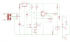
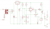
I am finally calibrating my thermostat circuit but have noticed that at the point of switching that the relay "chatters", switching on and off repeatedly. I thought it had something to do with the hysteresis pot but this is not the case.

The one thing that was pointed out in a previous post was that I had no smoothing on the power supply. This will be corrected but currently this is the circuit with the transformer supplying directly through the bridge rectifyier which measures 12.2V d.c. at the output.

The three pots are for the Range which is the desired range one wants the unit to operate in. The other is the Temperature which is the desired temperature within the Range that one wishes and the last is the Hysteresis.

The thermistor measures out at about 11k when at the desired temperature of 4°C.

Could the dirty supply be responsible? Any thoughts?

Cheers
Andrew
 

Attachments

  • Thermostat.png
    Thermostat.png
    11.9 KB · Views: 665
I think you need more hysteresis. The 4 degrees hysteresis might not be enough (I'm not sure how quickly temperature can change, but it might be that the thermistor isn't very stable causing the chatter). I don't think it's the relay coil's power supply. THey're not overly sensitive to power supply variations on the coil. But you should still have smoothing either way.

But this is just all my opinion.

EDIT: Wait a second, are you rectifying an AC voltage without any smoothing and using that as the power supply? In that case, that is definately the problem because then the term "power supply variation" is a misleading understatement! "Intermittent power" is more appropriate. It's like switching the circuit on and off at 120Hz since the unsmoothed AC half wave rectified signal jumps between full voltage and zero at 120Hz. I thought we were talking about a really bad linear regulator with no capacitors so the more like a variation of 10-20%, not 100%!

Look at the output waveforms of these rectifiers:
Rectifier - Wikipedia, the free encyclopedia
THat's the power going into your circuit. You need a capacitor smooth out the humps to get something even remotely like a constant DC supply.
 
Last edited:
Ok,

it's midnight here so will have a go again tomorrow a.m. Will put caps in the circuit tomorrow and check again.

Cheers
Andrew
 
Of course the relay will chatter. Your power supply has no smoothing whatsoever.

Its voltage goes from 0V to a positive voltage then down to 0V and back up to positive over and over at double your mains frequency.

Add a 1000uf capacitor to the positive supply.
 
Use big caps. (I'm thinking at least about 1000uF or larger, depending how much current your relay draws, you might be able to get away with 470uF.)

EDIT: Audioguru beat me to it :D
 
Last edited:
Once I made a thermostat very similar to that.

Chattering can occour in some OPAMPs, when V+ = V-.
I solved the problem by adding a 47uF or 470uF capacitor in the output transistor base.

Try to add a 47uF ~ 470uF capacitor before that 10k resistor, then after.
 
Last edited:
Well, I'm just saying the way I did and worked.

Mine did not have that hysteresis pot, though.
The comparator circuit without hysteresis has a voltage gain of 200,000 so it amplifies its own noise when the input is near the threshold voltage. The noise will cause a relay to chatter. Maybe your capacitor reduced the noise or stopped oscillation.
 
Just to emphasize what audioguru and dknguyen already stated:

Connect an alarm bell to the power supply and it will happily swing it's hammer. :D
 
The comparator circuit without hysteresis has a voltage gain of 200,000 so it amplifies its own noise when the input is near the threshold voltage. The noise will cause a relay to chatter. Maybe your capacitor reduced the noise or stopped oscillation.

Thanks for the explanation!
 
Hi,

thanks for the help guys it is much appreciated.

Popped a 4700uF 35V (was to hand) across the d.c output from the bridge, just before the L7812 and a 0.1uF directly after the L7812 from the output to ground. It's working like a dream.

Cheers
Andrew
 
Relay Chatter .. More questions?

Hi,

more questions if you will indulge me.

For the decoupling cap after the LM7812 in the below schematic I fitted a 600V type which was readily to hand, this is rather large and probably an overkill. I have discovered some 0.1M 16V ceramic disc caps in my goodies box, will these suffice for the application?

Secondly, as I was researching I seemed to get the idea that the power pins on the LM741 should also be protected by 0.1uF caps. Should I make allowance for these before sending the board in for manufacture. I assume that a cap would be in series between the relavant IC pin the relavant power rail.


Thanks
Andrew

PS: The 220V comes from a fused supply.
 

Attachments

  • Thermostat Modified.png
    Thermostat Modified.png
    12.8 KB · Views: 328
What is a 0.1M cap? Is it 0.1uF, if it is so, they will fit?

Actually those 0.1uF caps, for 7812, are just for filtering high frequency noise, from the 7812 itself and the large electrolytic capacitor.

For 741, the capacitor has to be in parallel with the pin, not series. For example, one lead in pin 7 another in GND.

I don't feel confortable with that 1A fuse before the 7812, why not add a fuse in the primary of the transformer, instead?
7812 will output 12W maximum, so add a 0.08A ~ 0.1A fuse for 250V. (If the outlet is 220V).
 
Hi,

Yes they are 0.1uF and they will fit as I am designing the board.

Is it a good idea to have those 0.1uf on the power pins?

The incoming supply is fused but will move the fuse for double protection.

Cheers
Andrew
 
Hi,

Yes they are 0.1uF and they will fit as I am designing the board.

Is it a good idea to have those 0.1uf on the power pins?

The incoming supply is fused but will move the fuse for double protection.

Cheers
Andrew

Yes. Add them in pin 7 and 7812 pin 3. It is always good to prevent some noise.
Add one in parallel with the 4700uF as well, but I believe that, depending on the xformer secondary, 16V will not be sufficient.

And, if you can, add a 47uf ~ 100uF capacitor in 7812 pin 3, as well.

If you want more protection, move that fuse to before the 4700uF capacitor, to protect it as well.
 
Your relay driver transistor might not turn off.
The output high voltage of the 741 opamp might be 1.4V less than the positive supply voltage. Then the voltage divider of R3 and R4 will allow enough base voltage for the relay driver transistor to be turned on when it should be turned off. Change R3 to 4.7k to fix it.

The 0.1uF to 10uF capacitor at the output of the regulator provides stability and improves the transient response when the load current abruptly changes.

I have never seen a ceramic capacitor with a voltage rating as low as 16V. My 0.1uF to 1uF ceramic capacitors are tiny and are rated at 50V.
 
Hi,

O.K. boys it's 00:30 and I am tired, thanks for the input. At 11:00 tomorrow I am off to the Kruger National Park for 7 days so no speakies for the same period. Will catch up on the return.

I have little comprehension of the technical arguments save to say that if Audioguru say's change to a 4.7k on R3 that is good enough me. I have little understanding of electronics and build by the numbers others so graciously offer.

Will post pic's tomorrow a.m. before I go on the caps, could have missed the boat on the value and voltage. The Cap Meter say's 0.096mF (0.1mF???) and the voltage on the caps say 16V but could have missed something. Anyways, they are cheap enough to buy the correct ones.


Cheers
Andrew
 
Going on a safari huh... Sounds neat, post pics of your adventure in the gen chat forum on your return.

Have fun.
 
Hi,

In an attempt to understand the circuit (so that I can tweak it) I did a little research on using the 741 as a comparator. I am using the circuit to control an absorption fridge and it switches an element on (cooling) and off (no cooling). I have needed to change the value of my NTC Thermistor from a 10k to a 4k7 and may need to change this again. Even though the circuit works perfectly the “Range” pot is at it’s extreme CW position. The change in thermistor resistance may have upset some “balance” in the circuit and I wish to understand this in order to fix it for any value of thermistor I may wish to adapt the circuit to.

Forgive the non-electronic jargon, this is how I understand the schematic posted below. My “reference” voltage divider is connected to the inverting input of the 741. One side of this divider is not fixed and can be preset through the “Range” pot which once set should remain static and then the “Temp” pot which is the temperature setting. As the NTC Thermistor gets cooler the resistance increases until it upsets the equilibrium between pin 2 and 3 on the 741. This causes the signal from pin 6 on the 741 to stop and the relay drops out and the element switches off.

The author of the circuit set the circuit up for a 10k NTC Themistor and his “Range” is 20 to 25°C. This would mean that the resistance sent from the 10k thermistor does not vary much from 10k as they are rated at 25°C. My circuit on the other hand would not work until I introduced a 5k thermistor. When approaching the setpoint that I desire ~ 3°C, my thermistor also measures in the 12k range.

From the little I understand the circuit as it stands should need no altering?

Secondly to better balance the “Range” and “Temp” pots. The former being set at ~10k (max) and the latter at ~2k to get the circuit to work. Should I place a 4k7 resistor in series with the “Range” pot which should effectively return the wiper to 50% of its scale?

Finally is the above is true does this mean that the two pots (10k and 5k) are the ones being used to balance the ~12k from the Thermistor.

These may be basic questions chaps but this is currently my level of expertise.

Regards
Andrew

PS: Will post safari pic’s soon.
 

Attachments

  • Final.png
    Final.png
    13.1 KB · Views: 276
Status
Not open for further replies.

Latest threads

New Articles From Microcontroller Tips

Back
Top