Continue to Site

Welcome to our site!

Electro Tech is an online community (with over 170,000 members) who enjoy talking about and building electronic circuits, projects and gadgets. To participate you need to register. Registration is free. Click here to register now.

  • Welcome to our site! Electro Tech is an online community (with over 170,000 members) who enjoy talking about and building electronic circuits, projects and gadgets. To participate you need to register. Registration is free. Click here to register now.

regulator LDO /1A problem

Status
Not open for further replies.

maryem

Member
Hello
I want to produce a 5V / 1A for PIC16F I have a transformer 230 / 5V, diode bridge and filter capacitor in the controller input, I find the voltage 4.18V with isis I tried with wregulator vin 2.2V / 10V but I do not have a voltage of 5V I get is 3.53V - 5V there a solution for you .thank you
 
Do you mean that the transformer is rated for 5.0Vrms, but at what current rating?
Are you using Silicon or Schottky bridge/diodes?
What is the filter capacitor value?
What regulator chip?
 
i used the transformer from WURTH ELEKTRONIK ( Transformateur d'isolation with 3 W,vin 85V à 265V,vout 5V) , standard power diodes 1N4007, capacitor2200uF, regulator
from TEXAS INSTRUMENTS LM2940IMP-5.0/NOPB Régulateur LDO , 0V à 26V, 500mV Dropout, 5Vout, 1Aout, SOT-223-3
 
A 3 watt transformer will not give you (5V x 1A = 5 watts).

5V AC rms = 7 volts pk.
7 volts - two diodes 7-1.4=5.67 DC (if the load is small and the capacitor is large)

The capacitor is too small. It will not hold up a 1A load for the time when the transformer is not sending power. At the peak of the power line the voltage is about 5.7 but will drop to about 2 volts when the power line crosses zero.
 
Is the "transformer" really a transformer???

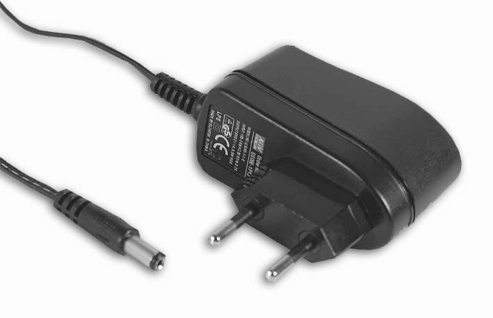
It looks like the input voltage is from 85v - 265v to provide a 5v output. A transformer can't do this. A switching regulated DC power supply can do this.

I'm guessing you already have a regulated 5 volts output...up to a maximum of 600mA.
 
Do you have a model number and picture of your transformer ?

It looks like it will power youth PIC directly.
 
upload_2016-6-30_19-32-42.png

upload_2016-6-30_19-33-26.png

upload_2016-6-30_19-34-30.png

We need more information on the "transformer". It might be a wall wort that outputs DC.
 
85v - 265v to provide a 5v output
Must be a transformer. It might have a tap for 110 in OR 220 in, but I can't do 85V to 265V in and get 5V out.
-------------------
Sorry to ask so many questions.
-------------------
The pictures of transformers you sent are not normally used in 50/60hz power line applications. So I will ask more questions.

1)This is a power line transformer. Two wires go directly to the power line. Usually the "core" is made of layers of metal.
VPS_36_DSL.jpg
3fd2.jpg
300.jpg

Here is a switching power supply. It could easy do 85V to 265V in and 5V DC out. The transformer does not connect to the power line directly. The core is usually made of a ceramic dark material.

SMPS.jpg
 
thank you for the reply I am sorry that I understood that I have to use before the transformer ceramic capacitors, but what they are for and how to calculate their values
 
To make 5V at the output of a regulator which has a drop-out voltage of 0.5V, the unregulated input voltage cannot ever be less than 5.5V at the specified load current of 1A. Using your 2200uF capacitor, the following simulation shows the effect of different transformer secondary voltages (V(rms) stepped from 5V to 9V in steps of 1V). The trace color progression goes green, violet, red, blue, pink...

I put in conservative values for the transformer source resistance R1 and the effective series resistance of the filter capacitor R2.

Note that you would have to use a transformer with a secondary voltage greater than 8V to supply 1A using 2200uF (The pink trace is the only one that wouldn't cause the regulator to drop-out). The dashed white line in the upper plot pane is the voltage that V(unreg) must stay above so that the regulator can work. Note the ripple current I(R2) that flows in the capacitor; make sure you buy one that will handle this...

378.png


You could make a more realistic estimate of current actually required, or use a larger capacitor, and that will reduce the transformer secondary voltage requirement a bit, but there is no way a 5Vrms transformer will ever work...
 
ok I understand what you say, the problem is the circuit size is too small which is why I chose this transformer seen its size and tried to adapt the max with my remaining circuit. all sizes of the transformer are too heavy.
 
If you want to build your own supply also look at this:
They have papers that include PCB layout, how to wind the transformer, part numbers. everything
Very simple parts. They are common in wall worts.
upload_2016-7-2_10-47-13.png


upload_2016-7-2_10-49-32.png
 
Status
Not open for further replies.

Latest threads

New Articles From Microcontroller Tips

Back
Top