Continue to Site

Welcome to our site!

Electro Tech is an online community (with over 170,000 members) who enjoy talking about and building electronic circuits, projects and gadgets. To participate you need to register. Registration is free. Click here to register now.

  • Welcome to our site! Electro Tech is an online community (with over 170,000 members) who enjoy talking about and building electronic circuits, projects and gadgets. To participate you need to register. Registration is free. Click here to register now.

Reducing voltage from 9 to 5 volts

Status
Not open for further replies.
Re: Where next....

Pallen33 said:
Point taken Tim, but my electronics knowledge is so poor that you may regret offering assistance!
you seem to be missing the point slightly, we are here because we want to help, if we didn't want to help, we wouldn't be here... Anyway, i was just trying to stir up some fighting spirit; spirit of the blitz and all that.

Pallen33 said:
C1, C2, C3 and C4 are in your diagram- I'd hazard a guess at capacitors on the basis of what's been said before, but what size should they be (10uF as you mentioned before??)
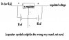
Correct, they are capacitors. Generally you can use whatever you like. I notice nigel only uses two capacitors, one either side of the regulator, both 1uF. Anything up to about 100uF should do the job (I don't think they even need to be the same as each other...). This is true whether you are using the variable regulator, or the fixed one.

Pallen33 said:
I'm also assuming that where the two parallel lines go off the diagram on the left hand side of the page that the top one would be connected to the +'ve terminal of the battery, and the bottom one to the -'ve side of the battery.
Again, correct.

smaller voltage regulators- they may well turn out to be the best option
If you are prepared to pay the postage that RS want (I think its a few quid) then it defenatly is the best option (fewer components, won't need any setting up etc), however, You said "go to maplin" so I assumed that it was close to you, and as the postage would probably cost more than the components themselves, it was probably worth getting the variable one form maplin and saving yourself the p&p. Just my opinion.

Tim
 
all good

Ok Tim, I'm going to have a go with a fixed 5v regulator first (just in case it does actually work) but if that dosen't do the business I'm going to dig deep, reach for the stars and go for the variable version because as you said, it doesn't actually look too bad

Just one point, why are there 4 capacitors because, for example, C1 and C2 seem to be doing the same thing in the same place, so can't you just put in a really big one instead of having two? (same goes for C3 and C4). Also what do the capacitors actually do (in suitably simple terms)? What is their function in the circuit?
 
Just one point, why are there 4 capacitors because, for example, C1 and C2 seem to be doing the same thing in the same place, so can't you just put in a really big one instead of having two? (same goes for C3 and C4). Also what do the capacitors actually do (in suitably simple terms)? What is their function in the circuit?

Well, i'm not an expert (obviously) but someone explained it to me as this: their function is to 'smooth' the power. when there is more voltage/current than usual, they will 'absorb it', and when there is less, they will discharge, making the the supply 'smoother'. In simple terms.

You probably don't even need a 'really big one', just one normal sized one would do fine. If you were running it from the mains, it would be different. Just one 10uF on each side of the regulator should do fine. Maybe the diag will help (i know it says 3.3v, but ignore that)
 

Attachments

  • reg3.gif
    reg3.gif
    2 KB · Views: 705
hopefull

Things are starting to look quite promising, I like the look of that new diagram a lot. I presume the chap which I've circled in the diagram (below) is the 5K Pot- my understanding is that this is basically a variable resistor, is this right and is there anything particular I should know about them?
 

Attachments

  • circuit_2.gif
    circuit_2.gif
    2.2 KB · Views: 703
Re: hopefull

Pallen33 said:
Things are starting to look quite promising, I like the look of that new diagram a lot. I presume the chap which I've circled in the diagram (below) is the 5K Pot- my understanding is that this is basically a variable resistor, is this right and is there anything particular I should know about them?

I'm afraid not!.

The diagram is for a fixed regulator, the symbol you circled is a 'ground' symbol - also the diagram should have a 'dot' just above it, to show the horizontal and vertical lines join.
 
oh yeh

Ok, now I feel stupid. I'm just going to print myself out a list of circuit diagram symbols so that doesn't happen again...

..right, I'm back in the game. I've taken the original circuit diagram (for a variable output current) and just crossed out what you suggested might be unnecessary capacitors and circled the 'Pot' (hopefully I've got it right this time). Is what I am left with (i.e. without the 2 extra capacitors) a suitable circuit to use if I want to adjust the output voltage? and back to my point pre-getting-the-circuit-symbol-wrong, is there anything particular I should know about 'Pots'?
 

Attachments

  • circuit_3.gif
    circuit_3.gif
    2.7 KB · Views: 698
lol, sorry, my fault.

The diagram is for a fixed regulator
as you had said you were going to go for a fixed regulator, thats what the diag was for, I just though it might tidy up all the bits and bobs that have been brought up the thread. I should have pointed that out.

Not sure why the dot didn't appear (I really need to get a different circuit drawing package, Tina is rubbish...)

I'm just going to print myself out a list of circuit diagram symbols so that doesn't happen again...
take a peek at http://www.kpsec.freeuk.com/symbol.htm, it has a lot of stuff on it, but it is useful reference

Is what I am left with (i.e. without the 2 extra capacitors) a suitable circuit to use if I want to adjust the output voltage?
Yes.

and back to my point pre-getting-the-circuit-symbol-wrong, is there anything particular I should know about 'Pots'?
There isn't much to know about pots, except, which legs are which! lol, on the diag, the part with the arrow is the middle leg, it doesn't matter which way round you connect the other two (one of them is unconnected anyway). But hang on, if you are going for the fixed regulator, you don't need the pot, thats only in the circuit for the variable regulator...??

Nigel, what would we do without you...?

Tim.

P.S. where abouts in Wales are you? just out of interest.
 
confusion

Yeh Tim, sorry it's all got a bit confused with the two circuit options. I'm going to try it with a fixed regulator first (just because it's simpler), but if that doesn't work then I'm going to go with the variable version and a Pot so I thought I'd get the low down on that as well whilst this is all in discussion. Right, I think that's been the most constructive day I've had at work for a long while..wish me luck as I attempt the different options over the weekend- I'll keep you posted with developments on Monday,
cheers, Paul
p.s Cardiff, but only pretending to be Welsh
 
Success!!

Tried the circuit with a fixed regulator and it worked!! thanks everyone, definitely couldn't have done it without all your help. No doubt I'll be back on the forum again with a new batch of amateur questions!
Paul :lol: :lol: :lol:
 
ummm, celebration may have been a bit premature

Not sure if my 'advisors' about this topic are still out there, or will read this thread again, but things haven't worked out quite as I thought so I need some advice again if that's ok...

Whilst the 5v voltage regulator was working ok in terms of producing the required voltage with a normal 9v battery, when I tried it with a bigger 8.4 volt radio-controlled-car-type battery the output from the voltage regulator was actually higher which meant it didn't work the device I am building. Anyway my conclusion was that one of those 3 volt voltage regulators might be just the ticket for my needs (even though the posting from RS is a bit on the steep side) so I ordered some and tried wiring one up in exactly the same way as the digram given before (see diagram at bottom of this post) with two 10 uF capacitors, but didn't get 3volt output, in fact didn't really get any output at all, all a bit weird. Is there something I'm missing here, or does this voltage regulator require a different wiring set-up? the voltage regulator I'm talking about can be found at the RS website, and has the stock number 349-4543

(it's the third one down just in case it's not highlighted red- it's the LM1086CT-3·3. This was the one I was previously advised might work for me)


[/quote]
 

Attachments

  • voltage_reg_circuit.jpg
    voltage_reg_circuit.jpg
    13.9 KB · Views: 653
The purpose of a voltage regulator is to regulate voltage. In layman's terms, it outputs a fixed voltage as long as the minimum input voltage requirements are met. The input voltage may change drastically, but as long as it's above 7V, the output should be around 5V for a 7805.
1. Ensure that the correct terminals of your 8.4V batt are connected to the 7805.
2. Ensure that the batt is giving out the correct voltage.
3. Ensure that your 5V and ground are not shorted.
4. Change a 7805 if all the above are satisfied.

Anyway, go to **broken link removed** and download the datasheet for the LM1086. Ignore all the crap but the diagram on very 1st page. You can see that the pinouts are different from a standard 7805. Modify your circuit and it should work.
Go ahead and dip your feet into some beginner electronics. I believe that's what got all of us started. :D
 
useful

Ah, right, I think the different wiring set-up is where I went so massively wrong- didn't even realise the top of a voltage regulator could be one of the inputs/outputs! In terms of my previous circuit diagram would I therefore connect the following bits to the following pins:

Vout= This is where I take the +'ve regulated voltage from
INPUT=This is where I put the +'ve unregulated voltage IN
'OUTPUT' and 'ADJ/GND' = Not sure what to do with either of these- is GND short for 'Ground'? If so is this where I connect both the input and output ground terminals to? sorry, I'm all confused because what do I then do with the OUTPUT terminal? It may be explained on that sheet you suggested, but I feel that I may not be able to understand the way it's presented and some of the terms used
 
i'm a bit supprised that you have an output terminal... I shall have a look at the data sheet when i have a free moment

'ADJ/GND' GND = Ground (as you suggested), ADJ = Adjust.

Normally, with a fixed regulator (as you had originally), the 'gnd' pin is connected to ground. Ground (in this instance) is the 0v (or negative) connection on the battery. This should also be connected to the 0v rail in the circuit you are powering.

However, with an adjustable regulator, this pin is connected to a pot (usually), which is used to adjust the output voltage - hence the pin is renamed 'Adjust'

Any help?

Tim
 
cheers

Yeh, thanks Tim, I'm clearer on the ground terminal now and how it might also be called 'adjust'. You've also hit the nail on the head with the confusion between the 'Vout' pin and the 'OUTPUT' pin- I'm not sure which one to take the regulated +'ve voltage from, although it sound like the 'Vout' but in that case what does the 'OUTPUT' pin do?? Any help on this distinction would be most appreciated.

Also, would it still be suitable to use 10uF capacitors with a 3.3v regulator as I plan to do, or would another capacitor value be more appropriate?

I thought I had it all sorted and then this 3.3v regulator seems to be set up all different...nothing's simple! :roll:
 
it if was simple it woudn't be so much fun... :lol:

10uF should be fine still

err, had a look at the data sheet, and it says that 'Vout' is the tab, and the 'output' is the middle pin. Someone may say that this is wrong, but personnally, I'd be tempted to try it using the 'output' pin as the regulated power, and leave the 'Vout' tab unconected. If it doesn't work, I was wrong!! Then if you heatsink it, make sure it is isolated from any other regulators.

I am assuming that your regulator is a T0220 (looks a bit like a flat transistor)? Because in my experince, having the tab as one of the conenctions on this style of case is quite rare. (You see it all the time on TO3 style cases, but not so much on T0220)
 
I guess you're right, but at the moment I just want an incredibly simple solution!

Ok, I'll give that a go Tim with the middle Pin as suggested, I'll try anything, and that may be one combo I didn't attempt in my frustration the other day..

Then if you heatsink it, make sure it is isolated from any other regulators.

not sure what you mean by 'any other regulators' - do you mean the other connections on the regulator?

You're right, the 3.3 v regulator I have does look like a flat transistor
 
not sure what you mean by 'any other regulators' - do you mean the other connections on the regulator?
lol, sorry I was just confusing things. What I meant was that if you built more than one regulating circuit (dunno why you would, but anyway), then you have another regulator, in this second circuit. And there is every chance that you would try and heat sink them on the same heatsink. Normally, this isn't too much of a problem, as the tab is connected to ground, however, if it is connected to 'Vout' (as it is on yours), then the heatsink may connect the tabs on both regulators together, which would cause some problems - this is why you use a lil' plastic thing, to stop this happenening.

don't worry about it, i was just trying to cover all angles.
 
Phew...

One things that got me thinking that things might be a bit different with the 3.3v regulator I bought was that in the name of it was "-3.3"
as in LM1086CT-3·3

Does the -3.3 mean anything crucial, like it will output a negative voltage or something equally weird?

Also, as a very general point, are heat sinks hard to fit because with the voltage drop from 8.4 to 3.3 volts my bad boy's bound to get a little hot under the collar...how much difference will a heat sink make?
 
had a look at the data sheet, and it says that 'Vout' is the tab, and the 'output' is the middle pin. Someone may say that this is wrong, but personnally, I'd be tempted to try it using the 'output' pin as the regulated power, and leave the 'Vout' tab unconected

Good call Tim, you were right- tried it last night and the output pin does appear to give the regulated voltage output, so thanks a lot. Supposedly then if I want to attatch a heat sink I can attatch it via the Vout tab at the top which should conduct the heat into the heat sink?

Thanks also checkmate- that information sheet saved the day! Much appreciated
 
Status
Not open for further replies.

Latest threads

New Articles From Microcontroller Tips

Back
Top