Continue to Site

Welcome to our site!

Electro Tech is an online community (with over 170,000 members) who enjoy talking about and building electronic circuits, projects and gadgets. To participate you need to register. Registration is free. Click here to register now.

  • Welcome to our site! Electro Tech is an online community (with over 170,000 members) who enjoy talking about and building electronic circuits, projects and gadgets. To participate you need to register. Registration is free. Click here to register now.

Reattaching ribbon cables

Status
Not open for further replies.

Pyjamausamah

New Member
Hi everyone

I'm pretty new to all of this, so please bear with me.

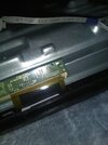
I'm attempting to replace a board that has some ribbon cables bonded/glued to it. I've attached an image showing this. When trying to attach the cables onto the new board, can I just haphazardly spread some conductive glue across the pads on the board, and place the cables on top, or would that end up shorting something? Is some sort of conductive glue a reasonable solution to this? Is there anything a novice would need to keep in mind when doing this?

Any help would be appreciated

Thank you
 

Attachments

  • IMG_20220113_182636055.jpg
    IMG_20220113_182636055.jpg
    3.7 MB · Views: 321
Only real solution is to try and find a replacement board with the cable attached.
I think I would be left with the same issue when trying to attach the other end of the cables as they also need to be glued down. And replacing the entire assembly would be too expensive. If that is the only practical solution, I might just sell for parts. I appreciate the help though.
 
One option is mechanical attachment, which some things use with similar flexible PCBs.

A strip of thin, hard rubber plus a metal bar, clamped down at either end to put continuous pressure on all the contacts.
 
If I really needed to do this, I think I do:

1642164557744.png

  1. Cut through the ribbon cable at the red line.
  2. Peel back the attached part (carefully) to the green line and bend up at 90°
  3. Bend the unattached portion (shaded) up at 90°
To remake the connection, use a needle an thread to stitch between the contacts -- even a 2-needle saddle stitch if your up for it -- to get something that looks vaguely like this. (Adding the stitching was going to be too much work!)

1642164833511.png


Then use a bit of thin (0.1.-0.5mm) tin or copper to make a shape like this:
1642164948015.png

And then pinch the metal above the contacts together:
1642165426167.png

Fun exercise in software; probably a step too far in reality.
 
Damn Buk... I appreciate the custom diagrams. But this may be a tier or two higher than anything I had planned o_O. Some tape will do just fine right? :p
 
no replacement boards that I've found online come with the cables attached
Hm. With some careful work with a fine point bradle, you could make a small hole through the flex board through each of the contacts, and then use a temp controlled iron to solder onto the board contacts through those small holes.

Notionally, something like this:
1642195674996.png
 
Last edited:
I'm 100% certain that I would mess that up, considering that I've only soldered once in my life, and that the contacts are the width of a hair.

One option is mechanical attachment, which some things use with similar flexible PCBs.

A strip of thin, hard rubber plus a metal bar, clamped down at either end to put continuous pressure on all the contacts.
Wouldn't rjenkinsgb's solution be suitable for a simple man like myself?
 
What is the pitch of the contacts?
(I'd been assuming they were about 0.5mm wide and 1mm pitch from the photograph.)
The width is approximately 0.5mm, and the pitch(distance between the contacts?) is about half that (it looks like the image has somehow blown up the pitch distance; it's a lot smaller in person)
 
The pitch is the distance between similar features -- the centres or left hand edges etc.

1642237860407.png

The easiest way to measure it is put a ruler on it and count the number of contacts in 1cm (1 inch if your of that persuasion) and then divide.

There are various 'standard' pitches in electronics. Historically, 1/10th inch (2.54mm) was used; but these days they are normally much finer.

A quick cast around it seems that for flex ribbons, 0.5mm, 1mm, 1.25mm and 1.27mm are the most common.
 
I'm 100% certain that I would mess that up, considering that I've only soldered once in my life, and that the contacts are the width of a hair.

Those kinds of ribbons often won't solder, and melt if you go near them with a soldering iron.

They are commonly used in LCD TV panels, where they are equally unreliable, but they are usually underneath the metal frame of the panel, and you can buy (or make) rubber strips which you wedge between the frame and ribbon, holding the ribbon in place, and applying pressure to make good contact. Needless to say you don't get a warranty on such 'repairs', but it can extend the life of the TV for a good many years. However, presumably there's nothing to wedge against in your application?.
 
You might get away with taping the ribbon in place and then putting a (tape covered) bulldog clip on from the other edge of the board.

Whether you'd have room for that isn't clear from the picture.
 
you can buy (or make) rubber strips which you wedge between the frame and ribbon, holding the ribbon in place, and applying pressure to make good contact.
This is what I was considering. There isn't really a place for me to wedge into between the frame and the ribbon, so I might go with some clamp or clip
 
Status
Not open for further replies.

Latest threads

New Articles From Microcontroller Tips

Back
Top