Continue to Site

Welcome to our site!

Electro Tech is an online community (with over 170,000 members) who enjoy talking about and building electronic circuits, projects and gadgets. To participate you need to register. Registration is free. Click here to register now.

  • Welcome to our site! Electro Tech is an online community (with over 170,000 members) who enjoy talking about and building electronic circuits, projects and gadgets. To participate you need to register. Registration is free. Click here to register now.

reading signal analizer

Status
Not open for further replies.
I downloaded Filter Pro but some issue with it or my computer, it won't run??
will try a different route.
aAs for filter types 2nd order 3rd order etc. I have no clue.
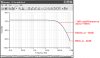
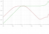
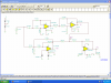
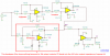
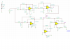
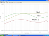
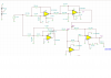
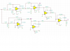
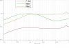
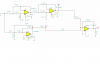
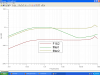
I have just been building circuits in TINA and seeing what the wave forms look like . I have a general idea what I is looking at but thats about it.
Been kinda do it and learn by doing.
Need to do more study but not real enthused about audio but its starting to grow o me. As I creat circuits, I wonder what it will do by adding this or that.
Found out what a summing amp is.
And maybe learn what noise cancellation circuit is good. Need to do some research and simulate.
 
A first order filter has a single resistor and a single capacitor. Its slope is very gradual.
A second order filter has two RC parts and has a sharper slope if it is active.
A 3rd order filter has very steep slopes.
A4th order filter is available as a "switched capacitor"' IC and has extremely steep slopes.
 
filter order

the steeper the slope the faster the response? At what point can one hear the target frequency from reading a wave form?
Here is Crutchows circuit but my results are way different??
Will recheck the schematic again but so far havn't found any discrepancies electrotech1..PNGelectrotech sche&#10.PNG??
 
the steeper the slope the faster the response?
What? A response does not have speed.
You are looking at simple 2nd-order filters. Each order uses a resistor and capacitor to make a slope that is 6dB per octave where an octave is doubling or halving the frequency. 6dB is double or half the amplitude.
So your lowpass filter is supposed to be -3dB at 2.8kHz, -12dB at 5.6kHz, -18dB at 22.4kHz etc. It has only 2 orders so at 100kHz it will still have an output.

At what point can one hear the target frequency from reading a wave form?
It depends on how loud is the original sound and on how loud is the background noise.
The levels on your graph are extremely low.

Here is Crutchows circuit but my results are way different??
His shows a bandpass filter for audio frequencies and yours shows a 2nd-order lowpass filter to reduce AM broadcast band radio frequencies.
 

Attachments

  • lowpass filter c&#11.PNG
    lowpass filter c&#11.PNG
    58.5 KB · Views: 140
Last edited:
WRONG input?

I assumed that the sinewave input, 1v , 60hz. (thats what Crutchow has but he has a second input at top of the screen? Assuming its a function generator?
I guess I need to get a different input or ??
have a different circuit but maybe I am going in the wrong direction??
Are the frequency curves anywhere right for app?
 

Attachments

  • hearing aid yes1..PNG
    hearing aid yes1..PNG
    41.9 KB · Views: 129
  • hearing aid yes c.PNG
    hearing aid yes c.PNG
    69.2 KB · Views: 121
MrDEB,
Please label your graphs.
You show a green trace from a highpass filter but your schematic has a different highpass filter.

You don't know what you are doing and we also don't know what you are doing.

Now you have the output of a bandpass filter U1 feeding a resistor R3 then R3 feeds into the extremely low output impedance of an opamp. The signal from R3 is shorted and does nothing. You can sum it with the output of your lowpass filter if your summing amplifier U2 has an input resistor from the lowpass filter. I don't know what the result will be.

Crutschow made a lowpass filter in series with a highpass filter (but it doesn't matter which one is first) making a bandpass filter then he inverted its output and summed it with the input.
 

Attachments

  • filter1..PNG
    filter1..PNG
    67.9 KB · Views: 123
  • error.PNG
    error.PNG
    21 KB · Views: 126
Sorry about that

Here is the graph with labels using a signal analyzer
also reconfigured circuit for summing amp as per suggestion
 

Attachments

  • waveform2 circui&#116.PNG
    waveform2 circui&#116.PNG
    33.7 KB · Views: 121
  • waveforns2..PNG
    waveforns2..PNG
    76.6 KB · Views: 121
I was wrong. Your U1 is not a Multiple-Feedback-bandpass-Filter. Instead it is actually an inverting 2nd-order highpass filter.
Why are you inverting it then summing it with your lowpass in series with a highpass bandpass filter?
 
Now im lost??
U1 filter is all by itself then U6 I assume is part of the summing amp as you posted? or did I misinterpret it??
All the filters came from a TINA example file.
I thought inverting amp had the input connected to the + input. TYhats the way the filter was derived from TINA file.
Will locate orgin and post.
 
circuit from TINA

here is the filter I am using. The bottom filter I posted earlier I need to locate
 

Attachments

  • 300-2.6khz..PNG
    300-2.6khz..PNG
    33.3 KB · Views: 137
Now im lost??
U1 filter is all by itself then U6 I assume is part of the summing amp as you posted?
U1 is an inverting 2nd-order filter followed by U6 which uis an inverter. If you made U1 a non-inverting filter like all the others then the inverter would not be necessary to do the same as your circuit.

I thought inverting amp had the input connected to the + input.
No.
 
revised circuit

are the results what you expected??
 

Attachments

  • waveformcircuit..PNG
    waveformcircuit..PNG
    33.4 KB · Views: 116
  • waveform2 circui&#116.PNG
    waveform2 circui&#116.PNG
    75.9 KB · Views: 113
The signal that you call "filter 2" is the input pin of the inverting opamp U6 that has no signal voltage.
Instead, the output pin of opamp U1 is the signal "filter 2" or you could show the signal at the output pin of the inverter U6.

As you can see at the output, the U1 and U6 opamp circuits simply attenuate the other signal so are absolutely useless.
 
well we dont want to kill the signal so do I insert another op amp to separate the outputs of U6 and U4 (kinda like a buffer?) or how to combine the two signals or do we want to (I guess if its to be connected to an amp the signals must be combined?)
 
revisions looking better??

changed a few things around. Didn't see the 100k gain resistors
 

Attachments

  • waveformcircuit..PNG
    waveformcircuit..PNG
    32.6 KB · Views: 113
  • waveforns2..PNG
    waveforns2..PNG
    46.7 KB · Views: 122
Isn't the combined output of the two filters supposed to be 0 db but its way down at -100 or is this correct so that the amp will perform right?
 
The output level is almost nothing because the output resistor R12 is almost a dead short at only 32 ohms. An opamp can drive 1k ohms with difficulty. Use 10k ohms.

Also causing the output level to be too low is because the upper bandpass filter and the lower highpass filter which has an inverter have opposite phases and they cancel. Try it without inverter U6 then maybe the filters will add instead of subtracting. Then the output of U1 drives R9. But maybe if you remove inverter U2 then inverter U6 might be needed.

You added inverter opamp U2 (an inverter, not a buffer) which is missing an input resistor so its input is a dead short to the output of U4. If it has an input resistor then it is an inverter which might not be needed. Try it without U2 and with the output of opamp U4 driving R11.

R9, R11 and R17 cause summing opamp U7 to have a gain of 100 which is much too high. Increase the values of R9 and R11 to 10k for a gain of only 10.
 
looks different

made revisions as suggested.
The combined is still below 0 db. Is this desired?
 

Attachments

  • waveformcircuit..PNG
    waveformcircuit..PNG
    28.8 KB · Views: 118
  • waveforns2..PNG
    waveforns2..PNG
    75.5 KB · Views: 116
The output now has a loss of almost 80dB so its level is only 1/10,000th of the input level. Maybe it is still cancelling the signal because U1 is still an inverting filter.

Why are you summing the non-inverting highpass/lowpass bandpass filter at the top with the inverting highpass filter at the bottom?

You said that your hearing has a loss of 60dB from about 250Hz to about 4300Hz. Then is your sensitivity normal from 20Hz to 250Hz and from 4300Hz to 20kHz?
 
Status
Not open for further replies.

Latest threads

Back
Top