Electro Tech is an online community (with over 170,000 members) who enjoy talking about and building electronic circuits, projects and gadgets. To participate you need to register. Registration is free. Click here to register now.
Welcome to our site! Electro Tech is an online community (with over 170,000 members) who enjoy talking about and building electronic circuits, projects and gadgets. To participate you need to register. Registration is free. Click here to register now.
I made a few changes to the code in which the increase and decrease buttons were working....
when i power on:
it displays "infrared liquid level detector"
then it displays "ENTER/SETTINGS"
BUT NOW its not repeating continuously and stops at the enter settings screen.......
when i press increase it increases
when i release increase it is stable
when i decrease it decreases
when i release decrease its stable
however pressing HOME and enter/settings has no affect
Code:
#include <pic.h>
#include "pic.h"
#include "delay.h"
#include "math.h"
#include <stdio.h>
#include <stdlib.h>
void FloatToStr(float , char[]);
void DelayMs(unsigned char);
void lcd_cmd(unsigned char);
void lcd_data(unsigned char);
void lcd_clear(void);
void lcd_puts(const char[]);
void lcd_goto_L1(void);
void lcd_goto_L2(void);
void lcd_cursor(unsigned char);
void lcd_init(void);
void init(void);
char WaitForInput(void);
void home_screen(void);
void EnterScreen(void);
void ShowDigits(unsigned char val);
void main(void);
void calc_distance(void);
#define LCD_RS RC0 //LCD RS pin
#define LCD_EN RC1 //LCD EN pin
#define LCD_STROBE() LCD_EN = 1; asm("nop"); asm("nop"); LCD_EN = 0
unsigned char cm10; //
unsigned char cm; //
unsigned int math; // used for voltage calculations
unsigned char NumDec;
unsigned char NumSep[2];
unsigned char i,j,k;
char temp[8];
int height=50, SensorPos=10;
char input_sw;
char mnuPOS;
unsigned char MyVal;
unsigned char MyValLCD[2];
unsigned char MyMaxVal;
unsigned char MyMinVal;
#define HOME_SW RC2 //HOME switch
#define INCREASE_SW RC3 //INCREASE switch
#define DECREASE_SW RC4 //DECREASE switch
#define ENTERSETTINGS_SW RA4 //ENTERSETTINGS switch
///////////////////////CONVERT FLOAT TO STRING///////////////////
// This function was taken from the CAVR library. It was modified slightly
// to suit our design.
void FloatToStr(float n, char str[])
{
float scale;
unsigned char d,f;
f=0;i=0;
if (n<0.0) {n=-n; str[f]='-'; f++;};
n=n+0.005;
scale=1.0;
while (n>=scale) {scale=scale*10.0; ++i;};
if (i==0) {str[f]='0'; f++;}
else
while (i--)
{
scale=floor(0.5+scale/10.0);
d=(unsigned char) (n/scale);
str[f]=d+'0';
n=n-scale*d;
f++;
};
str[f]='.';
f++;
for (j=0;j<=1;j++) //2 decimal points
{
n=n*10.0;
d=(unsigned char) n;
str[f]=d+'0';
n=n-d;
f++;
};
str[f]='\0';
}
///////////////////END CONVERT FLOAT TO STRING///////////////////
/////////////////////////////DELAY///////////////////////////////
void DelayMs(unsigned char cnt)
{
#if XTAL_FREQ <= 2MHZ
do {
DelayUs(996);
} while(--cnt);
#endif
#if XTAL_FREQ > 2MHZ
unsigned char p;
do {
p = 4;
do {
DelayUs(250);
} while(--p);
} while(--cnt);
#endif
}
void DelayS(unsigned char cnt)
{
for (j=0; j<(cnt*10); j++)
DelayMs(100);
}
///////////////////////////DELAY END/////////////////////////////
//////////////////////////////LCD SETUP//////////////////////////
/* send a command to the LCD */
void lcd_cmd(unsigned char c)
{
DelayMs(20); //wait for LCD to be ready
LCD_RS = 0; //write instruction
PORTB = (c & 0xF0); //load upper nibble on LCD data lines
LCD_STROBE(); //send instruction to LCD
PORTB = ((c << 4) & 0xF0); //load upper nibble on LCD data lines
LCD_STROBE(); //send instruction to LCD
}
/* send data to the LCD */
void lcd_data(unsigned char c)
{
DelayMs(20); //wait for LCD to be ready
PORTB = 0x00;
LCD_RS = 1; //write data
PORTB |= (c & 0xF0); //load upper nibble on LCD data lines
LCD_STROBE(); //send instruction to LCD
PORTB &= 0x00; //load upper nibble on LCD data lines
PORTB |= ( (c << 4) & 0xF0);
LCD_STROBE(); //send instruction to LCD
}
/*Clear the LCD*/
void lcd_clear(void)
{
lcd_cmd(0x01); //command to clear LCD
}
/*write a string of chars to the LCD*/
void lcd_puts(const char s[])
{
j = -1;
while(s[++j]!=('\0')) // send characters until null character reached
lcd_data(s[j]);
}
/*go to beginning of line 1*/
void lcd_goto_L1(void)
{
lcd_cmd(0b10000000); // command to go to line 1
}
/*go to beginning of line 2*/
void lcd_goto_L2(void)
{
lcd_cmd(0b11000000); // command to go to line 2
}
/*move cursor "x" positions to the right*/
void lcd_cursor(unsigned char x)
{
lcd_cmd(((x)&0x7F)|0x80);
}
/*initialise the LCD - put into 4 bit mode*/
void lcd_init(void)
{
LCD_RS = 0;
LCD_EN = 0;
DelayMs(20); //wait for LCD startup
lcd_cmd(0x28); // 4-bit mode
lcd_cmd(0x08); // display off
lcd_cmd(0x01); // clear display
lcd_cmd(0x0C); // disp. on, cursor off, cursor blink off
lcd_cmd(0x06); // entry mode
lcd_cmd(0x80); // initialise DDRAM address to zero
}
//////////////////////////LCD SETUP END//////////////////////////
void init(void)
{
[COLOR="Red"]MyVal = 0; //initializn these variables here
MyMinVal = 0;
MyMaxVal = 99;[/COLOR]
OSCCON|=0x60; //set fosc to 4Mhz
TRISB=0x00;
TRISC=0xFC;
TRISA = 0b10010010; // RA7 high imp, RA3 is serial out, RA4 button input
ANSEL=0x02; //set RA1 as analog input for GP2 sensor
ANSELH=0x00;
lcd_init(); //call LCD initialisation
}
char WaitForInput(void){
char done;
char temp;
done = 0;
while(!done){
if(!ENTERSETTINGS_SW){
temp = 1;
done = 0xff;
}
if(!HOME_SW){
temp = 2;
done = 0xff;
}
if(!INCREASE_SW){
temp = 3;
done = 0xff;
}
if(!DECREASE_SW){
temp = 4;
done = 0xff;
}
}//end of while
DelayMs(150); //debounce
return temp;
}
void EnterScreen(void){
lcd_clear();
lcd_goto_L1();
lcd_puts(" ENTER/SETTINGS ");
}
void ShowDigits(unsigned char val){
MyValLCD[0] = val /10; //returns the quotient (if temp = 35 the result is 3)
MyValLCD[1] = val % 10; //Returns remainder (if temp = 35 the result is 5)
MyValLCD[0] += 0x30; //to ASCII
MyValLCD[1] += 0x30; //to ASCII
EnterScreen();
lcd_goto_L2();
lcd_data(MyValLCD[0]); //to LCD
lcd_data(MyValLCD[1]); //to LCD
}
void calc_distance(void)
{
// from the transeiver datasheet the analog voltage is
// the inverse of distance, so distance can be calculated
// d = (1 / volts) then just scaled to suit the transeiver
// load ADC value in 16bit math var
math = ADRESH;
math = (math * 256);
math += ADRESL;
// now invert it; (1 / volts) use (6050 / volts) for scaling
math = (6050 / math);
if(math >= 2) math -=2; // fix linear error (-2)
if(math > 99) math = 99; // max limit at 99cm
// convert from 0-99 to 2 decimal digits, 0-99cm
cm10=0;
while(math >= 10)
{
cm10++;
math -= 10;
}
cm = math;
}
void home_screen(void){
lcd_clear();
lcd_goto_L1();
lcd_puts("INFRARED LIQUID"); //home screen message (line 1)
lcd_goto_L2();
lcd_puts("LEVEL DETECTOR"); //home screen message (line 2)
[B][COLOR="Red"] // i dont have a while(1) here any more[/COLOR][/B]
//[COLOR="Red"][B]Im calling the wait for input function here[/B][/COLOR]
input_sw = WaitForInput();
switch(input_sw){
case 1:
EnterScreen();
mnuPOS = 1;
DelayMs(50);
break;
//[COLOR="Red"]i made case2 go to the default case statement only since we in the home function[/COLOR]
case 2:
break;
default: break;// should any abnormalities occur
}
while(mnuPOS == 1){
input_sw = WaitForInput();
switch(input_sw){
//[COLOR="Red"]i made case1 go to the default case statement only since we in the home function[/COLOR]
case 1:
break;
case 3:
if(MyVal < MyMaxVal)
MyVal++;
ShowDigits(MyVal);
break;
case 4:
if(MyVal > MyMinVal)
MyVal--;
ShowDigits(MyVal);
break;
//[COLOR="Red"][B]i added this default case[/B][/COLOR]
default: break; // should any abnormalities occur
}
}
//Do something here with the new Value which is a decimal in MyVal.
//[COLOR="Red"][B]i added a return here[/B][/COLOR]
return;
}
void main(void)
{
init(); // initialise I/O ports, LCD
while(1)
home_screen();
}
This works great in protues but since my line 2 doesnt work i cant see the actual digits but in MPLAB i can see they are in fact increasing and decreasing:
Code:
#include <pic.h>
#include "pic.h"
#include "delay.h"
#include "math.h"
#include <stdio.h>
#include <stdlib.h>
void FloatToStr(float , char[]);
void DelayMs(unsigned char);
void lcd_cmd(unsigned char);
void lcd_data(unsigned char);
void lcd_clear(void);
void lcd_puts(const char[]);
void lcd_goto_L1(void);
void lcd_goto_L2(void);
void lcd_cursor(unsigned char);
void lcd_init(void);
void init(void);
char WaitForInput(void);
void home_screen(void);
void EnterScreen(void);
void ShowDigits(unsigned char val);
void main(void);
void calc_distance(void);
#define LCD_RS RC0 //LCD RS pin
#define LCD_EN RC1 //LCD EN pin
#define LCD_STROBE() LCD_EN = 1; asm("nop"); asm("nop"); LCD_EN = 0
unsigned char cm10; //
unsigned char cm; //
unsigned int math; // used for voltage calculations
unsigned char NumDec;
unsigned char NumSep[2];
unsigned char i,j,k;
char temp[8];
int height=50, SensorPos=10;
char input_sw;
char mnuPOS;
unsigned char MyVal;
unsigned char MyValLCD[2];
unsigned char MyMaxVal;
unsigned char MyMinVal;
#define HOME_SW RC2 //HOME switch
#define INCREASE_SW RC3 //INCREASE switch
#define DECREASE_SW RC4 //DECREASE switch
#define ENTERSETTINGS_SW RA4 //ENTERSETTINGS switch
///////////////////////CONVERT FLOAT TO STRING///////////////////
// This function was taken from the CAVR library. It was modified slightly
// to suit our design.
void FloatToStr(float n, char str[])
{
float scale;
unsigned char d,f;
f=0;i=0;
if (n<0.0) {n=-n; str[f]='-'; f++;};
n=n+0.005;
scale=1.0;
while (n>=scale) {scale=scale*10.0; ++i;};
if (i==0) {str[f]='0'; f++;}
else
while (i--)
{
scale=floor(0.5+scale/10.0);
d=(unsigned char) (n/scale);
str[f]=d+'0';
n=n-scale*d;
f++;
};
str[f]='.';
f++;
for (j=0;j<=1;j++) //2 decimal points
{
n=n*10.0;
d=(unsigned char) n;
str[f]=d+'0';
n=n-d;
f++;
};
str[f]='\0';
}
///////////////////END CONVERT FLOAT TO STRING///////////////////
/////////////////////////////DELAY///////////////////////////////
void DelayMs(unsigned char cnt)
{
#if XTAL_FREQ <= 2MHZ
do {
DelayUs(996);
} while(--cnt);
#endif
#if XTAL_FREQ > 2MHZ
unsigned char p;
do {
p = 4;
do {
DelayUs(250);
} while(--p);
} while(--cnt);
#endif
}
void DelayS(unsigned char cnt)
{
for (j=0; j<(cnt*10); j++)
DelayMs(100);
}
///////////////////////////DELAY END/////////////////////////////
//////////////////////////////LCD SETUP//////////////////////////
/* send a command to the LCD */
void lcd_cmd(unsigned char c)
{
DelayMs(2); //wait for LCD to be ready[b] shorter delay [/b]
LCD_RS = 0; //write instruction
PORTB = (c & 0xF0); //load upper nibble on LCD data lines
LCD_STROBE(); //send instruction to LCD
PORTB = ((c << 4) & 0xF0); //load upper nibble on LCD data lines
LCD_STROBE(); //send instruction to LCD
}
/* send data to the LCD */
void lcd_data(unsigned char c)
{
DelayMs(2); //wait for LCD to be ready[b] shorter delay [/b]
PORTB = 0x00;
LCD_RS = 1; //write data
PORTB |= (c & 0xF0); //load upper nibble on LCD data lines
LCD_STROBE(); //send instruction to LCD
PORTB &= 0x00; //load upper nibble on LCD data lines
PORTB |= ( (c << 4) & 0xF0);
LCD_STROBE(); //send instruction to LCD
}
/*Clear the LCD*/
void lcd_clear(void)
{
lcd_cmd(0x01); //command to clear LCD
}
/*write a string of chars to the LCD*/
void lcd_puts(const char s[])
{
j = -1;
while(s[++j]!=('\0')) // send characters until null character reached
lcd_data(s[j]);
}
/*go to beginning of line 1*/
void lcd_goto_L1(void)
{
lcd_cmd(0b10000000); // command to go to line 1
}
/*go to beginning of line 2*/
void lcd_goto_L2(void)
{
lcd_cmd(0b11000000); // command to go to line 2
}
/*move cursor "x" positions to the right*/
void lcd_cursor(unsigned char x)
{
lcd_cmd(((x)&0x7F)|0x80);
}
/*initialise the LCD - put into 4 bit mode*/
void lcd_init(void)
{
LCD_RS = 0;
LCD_EN = 0;
DelayMs(20); //wait for LCD startup
/*
lcd_cmd(0x28); // 4-bit mode
lcd_cmd(0x08); // display off
lcd_cmd(0x01); // clear display
lcd_cmd(0x0C); // disp. on, cursor off, cursor blink off
lcd_cmd(0x06); // entry mode
lcd_cmd(0x80); // initialise DDRAM address to zero
*/
//[b] These are my inits. Comment them out and use the above for you [/b]
	lcd_cmd(0x02);
	lcd_cmd(0x08);
	lcd_cmd(0x02);
	lcd_cmd(0x08);
	lcd_cmd(0x00);
	lcd_cmd(0x06);
	lcd_cmd(0x00);
	lcd_cmd(0x0E);
	lcd_cmd(0x00);
	lcd_cmd(0x01);
}
//////////////////////////LCD SETUP END//////////////////////////
void init(void)
{
MyVal = 0; //initializn these variables here
MyMinVal = 0;
MyMaxVal = 99;
OSCCON|=0x60; //set fosc to 4Mhz
TRISB=0x00;
TRISC=0xFC;
TRISA = 0b10010010; // RA7 high imp, RA3 is serial out, RA4 button input
ANSEL=0x02; //set RA1 as analog input for GP2 sensor
ANSELH=0x00;
lcd_init(); //call LCD initialisation
}
char WaitForInput(void){
char done;
char temp;
done = 0;
while(!done){
if(!ENTERSETTINGS_SW){
temp = 1;
done = 0xff;
}
if(!HOME_SW){
temp = 2;
done = 0xff;
}
if(!INCREASE_SW){
temp = 3;
done = 0xff;
}
if(!DECREASE_SW){
temp = 4;
done = 0xff;
}
}//end of while
DelayMs(150); //debounce
return temp;
}
void EnterScreen(void){
lcd_clear();
lcd_goto_L1();
lcd_puts(" ENTER/SETTINGS ");
}
void ShowDigits(unsigned char val){
MyValLCD[0] = val /10; //returns the quotient (if temp = 35 the result is 3)
MyValLCD[1] = val % 10; //Returns remainder (if temp = 35 the result is 5)
MyValLCD[0] += 0x30; //to ASCII
MyValLCD[1] += 0x30; //to ASCII
EnterScreen();
lcd_goto_L2();
lcd_data(MyValLCD[0]); //to LCD
lcd_data(MyValLCD[1]); //to LCD
}
void calc_distance(void)
{
// from the transeiver datasheet the analog voltage is
// the inverse of distance, so distance can be calculated
// d = (1 / volts) then just scaled to suit the transeiver
// load ADC value in 16bit math var
math = ADRESH;
math = (math * 256);
math += ADRESL;
// now invert it; (1 / volts) use (6050 / volts) for scaling
math = (6050 / math);
if(math >= 2) math -=2; // fix linear error (-2)
if(math > 99) math = 99; // max limit at 99cm
// convert from 0-99 to 2 decimal digits, 0-99cm
cm10=0;
while(math >= 10)
{
cm10++;
math -= 10;
}
cm = math;
}
void home_screen(void){
mnuPOS = 0;
lcd_clear();
lcd_goto_L1();
lcd_puts("INFRARED LIQUID"); //home screen message (line 1)
lcd_goto_L2();
lcd_puts("LEVEL DETECTOR"); //home screen message (line 2)
// i dont have a while(1) here any more
//Im calling the wait for input function here
input_sw = WaitForInput();
while(input_sw != 1); //[b] wait until enter is pressed[/b]
EnterScreen();
mnuPOS = 1;
DelayMs(2); //[b]shorter delay[/b]
while(mnuPOS == 1){
input_sw = WaitForInput();
switch(input_sw){
case 1:
mnuPOS = 2; //[b]This tells us the user finished entering[/b]
lcd_goto_L1();
lcd_puts(" Done! "); //home screen message (line 1)
break;
case 3:
if(MyVal < MyMaxVal)
MyVal++;
ShowDigits(MyVal);
break;
case 4:
if(MyVal > MyMinVal)
MyVal--;
ShowDigits(MyVal);
break;
default:
break;
}
}
DelayS(1);
//Do something here with the new Value which is a decimal in
//MyVal. The user is here because all data is entered
//i added a return here
//return;
//[b]im not 100% sure but since its a void i think a return isnt needed[/b]
}
void main(void)
{
init(); // initialise I/O ports, LCD
while(1){
home_screen();
}
}
tried your above code...
when i power up it displays:
"INFRARED LIQUID LEVEL DETECTOR_" clears then displays
"ENTER/SETTINGS" clears then displays..............
Done!.................
when i press HOME it goes to "infrared liquid level detector_"
when i release............................its stable and displays the same msg
when i press settings and release settings:
"INFRARED LIQUID LEVEL DETECTOR_" clears then displays
"ENTER/SETTINGS" clears then displays..............
Done!.................
when i press increase and release it
goes to "infrared liquid level detector_"
when i release............................its stable and displays the same msg
Sorry hay....i dont know why my browser was extremely slow today.
i noticed.............................
when i power on:
" ir lld" is displayed then "settings/enter" then "done!" and it repeats itself continuously...
when i press enter/settings 1st the same thing happens.....
BUT i noticed that i can only increase and decrease Whenever the ENTER/SETTINGS passes by otherwise if i press increase and decrease when done or "irlld" flashes by it goes to "ir lld aka home screen" and stops there completely.
even when enter/settings is not pressed 1st...as long as i increase and decrease when "enter/settings" flashes by...it will increase and decrease
pressing home displays "ir lld" only and halts there
lol Im SO happy!!!!!!!!!!!!!!!!!!!!!!!!!!!!!!!!!!!!!!!!!!!!!
Oh Oh i better stop b4 i get banned hehehe......
I tried the exact same code.....................BUT BUT BUT......my sixsense told
be that THAT..............CONFIGURATION BITS had something to do with it...........................
i didnt know which 1 to use....coz hehe im new to all this....
so i ran the code trying each type...i felt that the TYPE OF OSCILLATOR wasnt correct( it was set at external clockout) originally....But hehe i dont have any oscillator connected to the circuit...im using something internal of coz...so i tried the internal clock types:
internal RC clock out.............did not work BUT internal RC NO Clock worked...........
Now when i power on:
it displays "IR LLD" and stays there...no repeating
when i press "enter/settings"...it displays "enter/settings"
when i press "increase"....it increases
when i press decrease...it decreases.....
and ......when i press done.....it says done....and goes back to "ir lld"...
and i can go back to enter/settings if i want
wow..................Thanks AtomSoft......, You very helpful...
this is cool coz tomorrow the lecturer wanted to see some progress, actually every friday he wants to see progress....
so for tomorrow im going to show him the power supply and user interface
There are four items that are set when you "burn" the program into the PIC that are entirely separate from the program itself. These are set by supplying a configuration word which is burned into the PIC. The bits making up this word are formed in the line that starts...'__CONFIG'.
* Power up timer To prevent the program from starting too soon after the power is switched on, (everything may not be settled yet), you can activate a power up timer with '_PWRTE_ON'
* Type of Oscillator The oscillator you use for the PIC is either an RC oscillator, a crystal oscillator, (XT), a high speed crystal,(HS), or a low speed low power, (LP) crystal. Your circuit may not respond properly if you have the wrong oscillator type selected.
* Watchdog Timer To prevent your program from running off into 'never-never land' without the ability to recover, a watchdog timer, (WDT), can be activated. It will restart the program every 18 milliseconds or so unless a CLRWDT, (clear watchdog timer), command is executed during this period. Normally you don't want it activated,(_WDT_OFF). It can easily cause your program to seem to act strangely.
* Code Protection To prevent someone from copying the code you put into the PIC, you can 'code protect' PIC. Normally you don't want to do this and '_CP_OFF' is the default so you can leave it out.
heh cool!! i had mines on internal and even forgot to mention that to you glad to see its working on your side as on mines
" ir lld" is a lazy way of not spelling it all right?
Here is it in proteus: (second line wasnt working tho)
EDIT:
Forgot to note since i redid my PC (had a issue so reinstalled windows) i forgot to install Office(open office not ms) so im installing it now to see that lcd.doc stuff
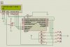
got line 2 to work with this init. its the same as yours but i had to tell the lcd first that we are using 2 lines. You should try it as to avoid errors in future:
Code:
void lcd_init(void)
{
	LCD_RS = 0;
	LCD_EN = 0;
	DelayMs(20); //wait for LCD startup

	lcd_cmd(0x02);
	DelayMs(5);

	lcd_cmd(0x28);	// 4-bit mode
	lcd_cmd(0x08);	// display off
	lcd_cmd(0x01);	// clear display
	lcd_cmd(0x0C);	// disp. on, cursor off, cursor blink off
	lcd_cmd(0x06);	// entry mode
	lcd_cmd(0x80);  // initialise DDRAM address to zero

}
Hehe...yeah i will be trying to program the GP212 to display measurements on the LCD....I'll definately be posting threads.....its 18:30 here. Im going to connect the sensor and take its output readings and compare it to the datasheet now...ill see you around...Take care
lol tried adding to your reputation again cause u deserve it but they dont allow that and say:
Was thinking of the same, are you planning on using the application for a aquarium sump. If it works on water I wanted to try the same and use it to control the top off water for the sump.
This site uses cookies to help personalise content, tailor your experience and to keep you logged in if you register.
By continuing to use this site, you are consenting to our use of cookies.

")
")