Continue to Site

Welcome to our site!

Electro Tech is an online community (with over 170,000 members) who enjoy talking about and building electronic circuits, projects and gadgets. To participate you need to register. Registration is free. Click here to register now.

  • Welcome to our site! Electro Tech is an online community (with over 170,000 members) who enjoy talking about and building electronic circuits, projects and gadgets. To participate you need to register. Registration is free. Click here to register now.

reading a 4x4 switch matrix

Status
Not open for further replies.
here is a better explanation on diodes in a switch matrix. NOTE I have removed the diodes from my revised schematic.
https://www.dribin.org/dave/keyboard/one_html/
Have a 2 x 4 matrix wired and hopefully try out the program today. I like Jons keypad in post #34 but what board are you using for the pic? looks similar to a Tap-28 and are you selling them??
 
...but what board are you using for the pic? looks similar to a Tap-28 and are you selling them??

It's my latest TAP-28 design that adds a USB serial interface using a CH-340 USB chip. Love that chip because it doesn't have the driver issues of the FTDI and Prolific chips...nor the price tag.

When I designed the original Tap-28 boards, getting printed circuit boards made was a different game. To get boards made cheaply, you had to buy a hundred or more. That's the reason I sold them to others - we could all benefit from a large buy.

These days, when you can get a 100mm × 100mm board for 50 cents, selling boards doesn't make sense. The effort to provide documentation, the hassle of shipping and customs froms can't be justified. Trying to sell bare boards for $5 - $10 each doesn't fly, no matter how superior they are.
 
Came up with an additional feature for this project. In between rounds of play the scores (# of dominos are added up) . Then the next round of play is started which lasts about 20 minutes. Thinking of having one key to turn off the LCD display and put the pic to sleep, to save the battery. Question is if no info displayed on LCD is there a substantial drain on battery? If so then a simple mosfet on the LCD Vdd input. As for SLEEP there is no SLEEP statement in Swordfish but have seen reference to using the SLEEP module.
When the pic is in SLEEP mode will the data that has been entered be lost??
Any suggestions
 
The SLEEP MODULE has everything in it. Will maybe use if the project uses too much battery juice while sitting idle. My plan is to have one of the leftover switches control the sleep when needed? Want to first see what amount of current is used while sitting idle.
MODULE Module_Sleep
// IMPORTANT: dont forget "Config WDT = On" in main program
// let compiler know we are using WDT - don't forget
// to set WDT fuse when programming into MCU!...
#option WDT = true
// generic sleep command...
PUBLIC INLINE SUB Sleep()
ASM
Sleep
END ASM
END SUB
// Sleep for pSeconds - assumes default WDT postscaler of
// 1:128 - note this is an approximate time and is influenced
// by such things as temperature - see datasheet for more details -
// granularity is approx 2 seconds...
PUBLIC SUB Sleep(pSeconds AS WORD)
INC(pSeconds)
pSeconds = pSeconds >> 1
WHILE pSeconds > 0
Sleep
DEC(pSeconds)
WEND
END SUB
 
How many kW you running the leds at? You could drop the led current to around a couple of mA and save alot of battery life, much more than trying to get the pic to sleep without using a hammer.
I use modern Leds at roughly 1-2mA and they show up fine, you dont need 20kW to see a modern led.
 
It's not the leds I am concerned with and in the schematic I posted there are only two LEDs being used to indicate the battery condition thus looking at large value resistors.
The LCD display is what I am concerned about draining the batteries in between rounds (aprox 20 minutes per round x 13 rounds).
After I get an LCD and matrix wired up on a perfboard I am going to measure actual current drain.
 
With no backlight on and the contrast set correctly, or a segment LCD you will use next to nothing. The backlight on the LCD will use the most, the actual LCD uses very little, and your not updating the display unless the values change are you??

Hook up the back light to a light dependent resistor and have the nicro decide if you need the back light and by how much. Turning off the backlight for 20 mins will save you more than the sleeping micro will in a year.

those two LEDS..... 1-2 mA max ;). Stop making a fuss about spiders when you got a lion 3 feet from you.

Your schematics and my glasses are incompatible
 
Good point on the backlight. After I get my switch matrix wired up on a perf board and the LCD soldered on I intend to investigate what is and what isn't needed.
The light dependent sensor sounds like a candidate but?? I have extra switches and thinking of using one for turnng the LCD off or maybe just the backlight?
 
You're talking about putting the micro to sleep to save some tiny amount of power but you hadn't considered turning off the back light of the LCD when it's not in use.... Have you considered the power budget at all? How much energy is in what, 3 AA cells? How much power will the LEDs draw during game play? How much does the micro add to that?

If I have understood correctly, the LCD* is used only at the end of the game to add up scores. Why have it on at all doing most of the game? What current does the LCD draw with and without the backlight on? How much will this impact run time?

Why have a sleep mode at all during breaks in play? If the only thing you need to remember to re-start is the player positions in use, why don't you store them in EEPROM, and read them back after a "pause?"

It would make sense to figure out your power budget now, so you will know if you need to do all these things to get a reasonable run time. Sure, putting the micro to sleep may add some seconds to run time, its current draw will be so much less than everything else as to make no difference.

* You are aware that you need an LCD designed to run off 3 volts for you application? An LCD designed for 5 volt operation will probably need a bias voltage of less than 0 when operating off 3 volts.
 
350mA -750mA for the lcd back lights of many the normal cheapo Chinese ones. The segment display LCD's can run as low as <10uA even when on, check out the ones on the say the sil labs Gecko boards. I have a gecko board that tell the time,takes temperature and humidity reading every 5 mins and displays it all the time, so far my single cell watch battery has powered it for just over 2 years.

Your 3AA batteries are likely to last no more than maybe a day tops.

If you dont want a LDR on the display then use a pot to drop the light output, you rarely need a lcd full wack unless the sun is bright, assuming your using a hitachi type lcd then put a pot or trimmer on pin 3 (rusty memory but i am pretty sure its pin 3 for contrast) and adjust the LCD contrast and back light to get a hal decent display. I have both types of LCD with and without backlight, in most situations i have never needed the back light.

Most of mine pull around 350mA but a few pull 750mA, with a pot on or..........pwm (please pick pot) you can drop this right down, i think most situations with a backlight you can get away with 10-20% pwm so turn the backlight right down.

One the most common mistakes is constant updating of the display, the program on each loop outputs the display regardless if its changed or not!! What is the point of writing the same thing to the display each loop? No idea if your code does this i havnt looked, i wont look as i promised myself i wouldnt look.

Seriously though your micro in sleep will save nothing compared to dropping leds, turn off the back light until needed. Why use a switch? Just have the micro turn the light on or off via a transistor or LLMosfet.
Its 2018, how tacky and stone age to reach over for a switch just to see the screen? If it is only used mainly at the end then when the micro does the final output get it turn on the back light, wiggle it with pwm and have a low duty cycle, its only about 4 years of code to that.

You could get the Lcd to flash an asterix on and off every few seconds as a kind of heart beat. Two leds not directly in the game are 40mA of pure waste, sleeping the micro wont get you that back. On the gecko board it sleeps, but with that it wakes every five mins and takes the readings, it displays them and the display stays on when the micro is asleep. You dont have the right chip for those displays however as they need a driver on the chip and alot of pins.

But you can get close to it, do a software step map of the game. They save you loads of effort, work out what you need on and when. BTW cap touch switches use very little current.... What you like on cap touch Johnsea? lol
 
The 3v for the LCD is a consideration that I realized. The backlight is truly the main battery drain culprit.
The calculator is turned on
The player enters their score
calculator is put off to the side until the present round of play is over
Player then enters the score for that round of play
this scenario occurs 13 times during the game
The EEPROM is on my list to experiment with (never used the EEPROM contained on a pic)
The backlight controlled by a mosfet/port pin is o my list as well
search for a 5v LF pic reasonably priced and able to perform duties required of it and in a smd package.
 
No its not the 3V that matters, its the 350-750 mA that matters.
Stick resistors or pots on to save the juice. FRAM is better than EEPROM.
 
I realize the back light consumes lots of juice so a simple mosfet controlled by a port pin should take care of the back light drain.
I am working on a switch matrix and an lcd proto-type perf board and going to test just what kind of battery drain I am loking at controlling.
I will post results as I get them,
A tactile switch that is an extra switch in the 4x4 matrix should take care of this by switching a port high and low.
 
Just run the micro dead slow, you dont need Mega Hertz for that kind of thing IMHO, 20mA for leds was for when they used them in the Ark. Most the tiny smd ones I have are really bright at 1mA, so with 2 leds that 38mA you have saved and if you look at the data sheet it should give you a rough idea of power draw at different processor speeds. Cut power to the LCd when not in use bu using wake on change or whatever, there is no reason you shouldnt get months out two cells! Even using a single AAA you should get a long time with some trickery.

Long time since i played with cap touch stuff, but oddly enough my bio reactor looks like its going to use it for some parts.

Out of interest do you plan out your projects first, or do you kinda just get an idea and follow from there? These days i tend to try and plan everything first, not being the best coder in the box i find software flow charts really useful. Which is what I have started for the flo controller, I got my stir mechanism coming back this week. I had to have a lock pin machined off so i could get into it to see the connections.
 
I plan out what I want the project to do--write out a list with scenario of what the user is doing.
Then I draw out a basic schematic using diptrace while I am writing preliminary code. While writing the perlim code I discover issues that need to be addressed.
On this calculator I have discovered some slight issues such as battery drain issue. So now I need to insert a mosfet on my schematic to have the pic turn OFF the Vdd and back-light to the LCD.
Then build a proto- type on a perf board and measure the current draw.
 
MrDEB,

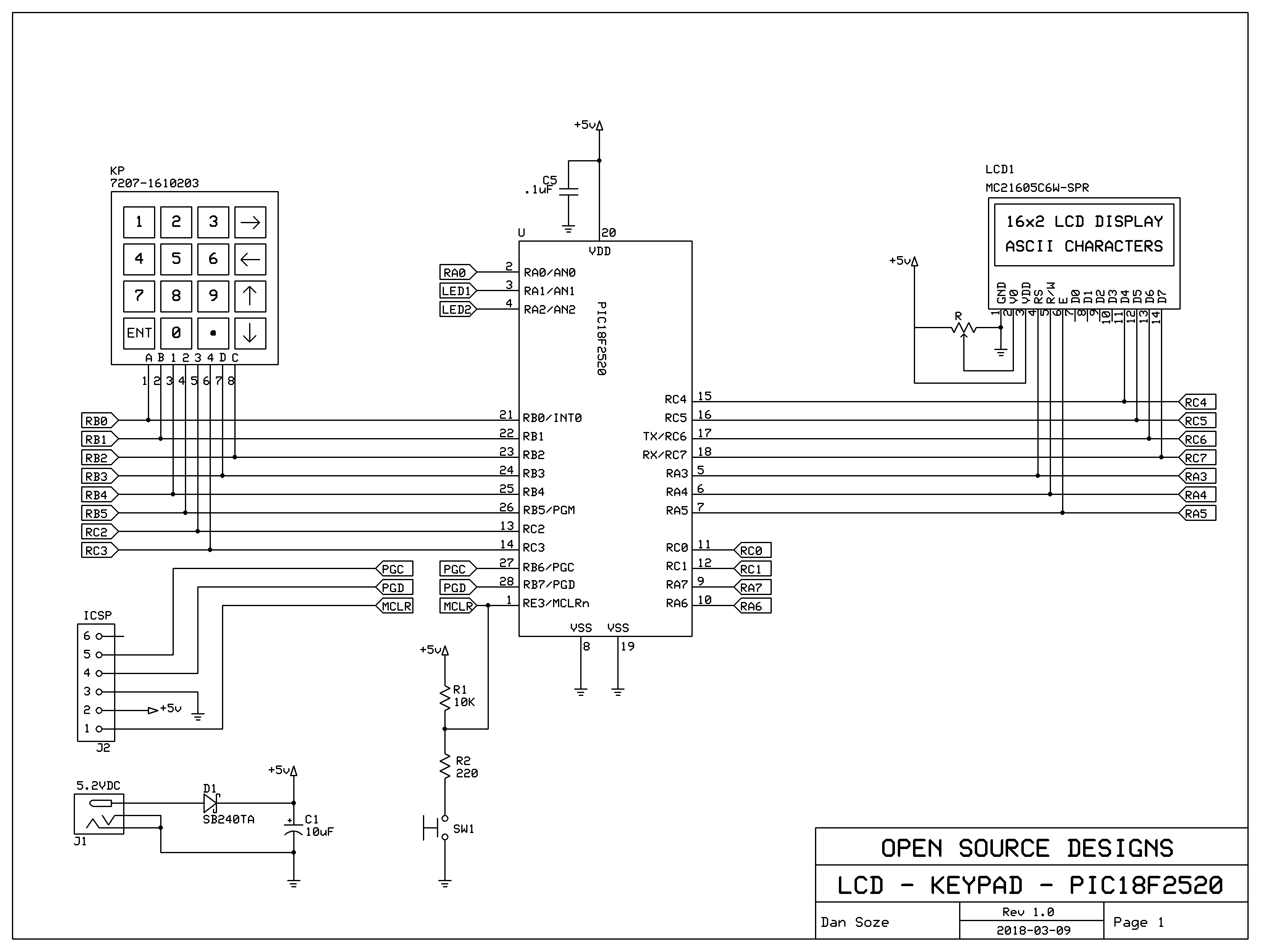
I built a prototype of your project with a PIC18F2520 (sorry I don't have a PIC18F24K20 handy).

This is my schematic:
18F2520_LCD_4x4kp.png


You can find my complete project on GitHub here.

The source code is done with the Microchip XC8 compiler. It will also compiler for the PIC18F24K20 but I do not have any to validate it. Every thing works with a PIC18F2520 so I believe that it will work for the PIC you selected.

Be warned that my circuit is similar to yours but not the same. I assigned the pins in a way to make In-Circuit-Debug possible.

<EDIT>
Followup on how much current this design is using.
My LCD is an genuine Hitachi HD44780 module, the PIC18F2520 uses a system clock of 500KHz, 125000 instructions per second. The total current draw is 1.5mA at 5.0 volts. Using three AA cells with at least a 1950mAH capacity will run this circuit for up to 1300 hours or about 50 days.
 
Last edited:
I plan out what I want the project to do--write out a list with scenario of what the user is doing.
Then I draw out a basic schematic using diptrace while I am writing preliminary code. While writing the perlim code I discover issues that need to be addressed.
On this calculator I have discovered some slight issues such as battery drain issue. So now I need to insert a mosfet on my schematic to have the pic turn OFF the Vdd and back-light to the LCD.
Then build a proto- type on a perf board and measure the current draw.
At the moment my mind has gone blank, but there is a free mind map type program with a simple to use software flow chart template. Give it a try, honestly if like me code dosnt come natural to you, then simple block layouts really help when coding.

All you do is put the major steps in and how they link, its mothers day tomorrow (mines getting a bath pampa kit funny enough) but if i get time i will do you a really simple flow chart. Honestly unless your good at code it does help a great deal.

I used to do it your way (sort of), the problem is things change at the early stages and your code becomes a mess. If you have a basic flow chart you keep updated it makes life simple.

As for your schematics i can rarely read them, not sure if its a contrast issue or what! But even with my glasses on i struggle to read the values and writing, if dip trace allows colours try and put some contrast in.
 
Status
Not open for further replies.

Latest threads

New Articles From Microcontroller Tips

Back
Top