Continue to Site

Welcome to our site!

Electro Tech is an online community (with over 170,000 members) who enjoy talking about and building electronic circuits, projects and gadgets. To participate you need to register. Registration is free. Click here to register now.

  • Welcome to our site! Electro Tech is an online community (with over 170,000 members) who enjoy talking about and building electronic circuits, projects and gadgets. To participate you need to register. Registration is free. Click here to register now.

Reading 48v ebike battery voltage to esp8266

Status
Not open for further replies.

Morton

New Member
Hello, i am new to this forum and also to most of the electronics.
I am building "smart home" dashboard on home assistant application and I want to include my electric bike battery voltage. I plug bike to charger everytime i am back from work. (charger itself not always on, i turn on and off once charged)
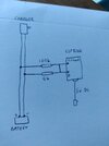
My plan is to tap into charger wire that goes to ebike.
Expected voltage is 48-55v, making max voltage of 60v to be safe.
I would use esp8266 wifi board to read voltage via analog input pin.
My main issue is making sure i get devider correct to 3.3v at most for analog input.
I wonder if you could help me with that.
Devider Calculator shows i could use 2megaohms resistor on positive and 110k on negative.
Does that sound right? Could i have any issues with this solution? For example when battery is charging?

Thanks
 
You calculation looks about right. You will get about 1 volt for every 20 V of input.

However, back in the real world, 2 MOhms is a large resistance and the tiniest bit of moisture will give comparable resistance which would make the readings inaccurated. I don't know what the input resistance of the esp8266 is, but many analog to digital converters will take pulses of current, which can reduce the voltage if the supply has a high impedance.

I suggest much lower resistors, maybe 100 kOhm and 5 kOhm. I would also put a capacitor across the 5 kOhm resistor. 1 uF would be plenty, but larger values would be fine.

There is little downside in having lower value resistors. They will take more current, but still nothing compared to the charging current. If they were to be connected to the battery all the time, they would discharge the battery, but 100 kOHm would be less than 0.6 mA so a 1 Ah battery would discharge in 1600 hours, so it's still not significant. If the resistors are across the charger output and the charger is disconnected when not in use, there will be no effect. Even if the charger measures the current taken by the battery, the extra 0.6 mA will be tiny compared to charging rates that will be at least 1 A for any realistic speed of charging.

I guess your battery will be much larger than 1 Ah, making 0.6 mA negligible.

The heat loss in the 100 kOhm resistor will be about 33 mW when connected, so it might get warm enough to feel the heat if you put your finger on it, but only just.

If you chose to go down to a 10 kOhm resistor, you might start to get some detectable heat, and the discharge current might start to be an issue, although I doubt it. Lower that 10 kOhms would mean having to worry about the resistor power, so I don't recommend that.
 
Hi Diver300, thank you for suggestion and detailed explanation.
I will try using 100k and 5k resistors. Just i have further question on how capacitor should be connected.
I did quick non technical drawing of my circuit. Can you please see if that is how it should be connected? I am not sure if tapped ground should be feed into ground pin of my esp8266. And if you could give some more details on exact capacitor location would be great.
 

Attachments

  • 16452876388374800777679521246316.jpg
    16452876388374800777679521246316.jpg
    3.3 MB · Views: 349
charger.jpg


This is how the sensor should be connected.

You should be able to measure around 2.6 V across the input to the ESP8266 when the battery voltage is 55 V.

The capacitor should be connected across the input to the ESP8266, which is also in parallel with the 5 kOhm resistor.
 
Not read the whole thread yet but just want to point out the ADC on the ESP has a max voltage of 1V.

Mike.
 
is it possible to read voltage between each cell with a esp8266 ?
I have 4x 12v deep cycle batteries and wanting to know voltage of each battery after the melt down I recently had
I had 1 battery die and drop to 8v and the battery on the other end ended up getting cooked at 17v
 
Dead simple - four attenuators feeding four A2D inputs, except the ESP8266 only has one as I recall?. You could either use a better device (like an ESP32), or use an analogue switch to select which attenuator you want to read (which is all that happens internally with multiple A2D inputs anyway).

By reading the voltage on the +ve of each battery, you can very simply use a one bit of maths to calculate the individual battery voltages.

Any idea why your batteries failed?, were they identical? - same make, same type, same age etc.

I presume you replaced all four batteries with new ones?, if not you're asking for trouble, you should never mix different batteries, or different age batteries.
 
ok so all I need is an ESP with 4x ADC pins
so your saying read battery
#1 12v
#2 24v
#3 36v
#4 48v

and just use math to find the differences


These 60kg batteries SBS190F


pretty much these are the things the ESP device needs to do

Measure Voltage of 4x 12v batteries (Ideally find a way for it to run from the 48v bank but the 220v Inverter has USB)

Operate a 12V Relay that is controlled by ESPHome with Home Assistant
that is being activated by Water Temp that then runs a 100A SSR that runs immersion heater

Their was something else but can not remember ... maybe I was going to log the watts being used as well

pretty much I have a 30A MPPT charger doing 190ah worth of batteries , the charger is set with a 52v low voltage settings so it will only energize its load output when batteries are nearly full , I am powering the 12v relay and the SSR from a voltage divider I think it was 3k and 1.8k resistor , when the SSR is active it runs a 1kw immersion heater
then I have a 300w inverter that runs a 100w air pump for aquaponic system

when battery drops below 52v the relays all stop as load output stops its pretty much just to dump excess power into heating when temp is below threshold


which would you use


Last edited:
Note all, we've gone from e-bike batteries to deep cycle lead acid batteries.

Mike.
 
ok so all I need is an ESP with 4x ADC pins
so your saying read battery
#1 12v
#2 24v
#3 36v
#4 48v

and just use math to find the differences

Yes,

Battery 1 = #1
Battery 2 = #2 - #1
Battery 3 = #3 - #2
Battery 4 = #4 - #3


These 60kg batteries SBS190F


pretty much these are the things the ESP device needs to do

Measure Voltage of 4x 12v batteries (Ideally find a way for it to run from the 48v bank but the 220v Inverter has USB)

Operate a 12V Relay that is controlled by ESPHome with Home Assistant
that is being activated by Water Temp that then runs a 100A SSR that runs immersion heater

Their was something else but can not remember ... maybe I was going to log the watts being used as well

pretty much I have a 30A MPPT charger doing 190ah worth of batteries , the charger is set with a 52v low voltage settings so it will only energize its load output when batteries are nearly full , I am powering the 12v relay and the SSR from a voltage divider I think it was 3k and 1.8k resistor , when the SSR is active it runs a 1kw immersion heater
then I have a 300w inverter that runs a 100w air pump for aquaponic system

when battery drops below 52v the relays all stop as load output stops its pretty much just to dump excess power into heating when temp is below threshold


which would you use


Do you need WiFi?, if so any ESP32 should be fine as long as it ha enough I/O pins.

If you don't need WiFi then pretty well any processor will be fine.
 
If you had issues with accuracy of A/D or wanted to add capability like
energy consumption over time or seat temperature :))) or whatever.
There are chips out there, like this one, that has a +/- .1% Vref onboard,
and its ADC can common mode outside its rails, allowing a shunt to be
placed in negative lead so you can monitor power/energy used, charged.

Single chip. Could also handle heart rate..... Note chip does not have WiFi, so still
need ESP8266. Does have SD Card capability as well.

Note this shows a fraction of overall chip resources used.

1651146771836.png


Onchip resources -

1651146846225.png


Regards, Dana.
 
Last edited:
Status
Not open for further replies.

Latest threads

Back
Top