Continue to Site

Welcome to our site!

Electro Tech is an online community (with over 170,000 members) who enjoy talking about and building electronic circuits, projects and gadgets. To participate you need to register. Registration is free. Click here to register now.

  • Welcome to our site! Electro Tech is an online community (with over 170,000 members) who enjoy talking about and building electronic circuits, projects and gadgets. To participate you need to register. Registration is free. Click here to register now.

RE: 1 Second Time Base (ACCURATE)

Status
Not open for further replies.

D'COUNCILOR

New Member
Hello Everybody :)


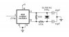
I need a schematic of 1 second time base for my count down timer. Please help me I would really appreciate your help to me.
thank you and god bless.

D'COUNCILOR
 
555?

Is it the one that counts from 6-0? I would say that a 555 timer, in astable mode, should be okay. The accuracy depends on the components used, ie, a 20% tolerance resistor would be somewhat like the brittish bus system :shock: . What is it counting for anyway?

The 555 astable circuit can be found at pretty much any electronics site! It is a very common circuit.

Hope this is of some help...

-Chris
 
For accuracy, you'd be better off using a crystal-based oscillator, at a higher frequency, then dividing down the pulses, for example, use a 16kHz crystal (16384 Hz), and divide by 2^14.
 
i thought of something, but i don't know if it's accurate enough....
the idea is to take th 50/60Hz frequency from the mains and divide it with a 5/6 divider and a 10 divider such as 4017 or something else...
hope i helped :p
 
That could also work quite well - though the mains frequency does fluctuate about 0.1%.

Bear in mind also, that you would probably first rectify the negative half-cycle, and hence the frequency would double, to 100/120 Hz.

I'm not sure if it's of any consequence, but in areas where ripple control is used for off-peak switching, a 400-1200 Hz signal is injected into the mains, in the evening and the morning. This may or may not affect timing.
 
60 Hz

Hi, I'm wondering if anyone could tell me what should I do to the AC frequency before feeding it to a 4029 (or so) to divide them...

All I've thought of so far is using a diode to get it straight to 60Hz instead of a bridge rectifier (to avoid doubleing it), but what do i do then? Do i need to change the waveform or anything?

I just want the easy and fast way of using the 60hz cycles of AC to get a 1hz "¿precise?" clock pulse...

For demonstration purposes only, don't care if it's not actually precise...

Thanks!!!
 
Check the green area of this schematic.
I believe it is a 1Hz divider from mains 50Hz.
on pin 12 of the 2nd 4017 you have 1hz.

Good luck. :wink:
 

Attachments

  • frequensmetre_sam.gif
    frequensmetre_sam.gif
    62 KB · Views: 816
Pulses

Do you think it will work on 60Hz input?

I guess I will have to work on the dividers to get it going but it should, my problem was for the dividers to support/recognise the pulses...

What's the N8 though??? how do I get it going? lol

Thanks!!!
 
hey! isn't it a NAND gate???
ok now I know what's up...
but still in doubt...

what's the 4017?
 
If your mains running on 60hz you'll got 1.2 Hz or 1.02, do the math yourself :D
I found something else, its give you 2 Hz, what you can divide again or find the right XTAL"Crystal" for your need's. :!:
 

Attachments

  • 2Hzclock_731.jpg
    2Hzclock_731.jpg
    10.9 KB · Views: 591
Yes, i'd seen that 4060 circuit before, i'm using it as well, the thing is, i'm trying to demonstrate different ways to drive a clock, so i need both methods.

thanks!
 
Status
Not open for further replies.

Latest threads

New Articles From Microcontroller Tips

Back
Top