Continue to Site

Welcome to our site!

Electro Tech is an online community (with over 170,000 members) who enjoy talking about and building electronic circuits, projects and gadgets. To participate you need to register. Registration is free. Click here to register now.

  • Welcome to our site! Electro Tech is an online community (with over 170,000 members) who enjoy talking about and building electronic circuits, projects and gadgets. To participate you need to register. Registration is free. Click here to register now.

RCD snubber for IGBT inverter..

Status
Not open for further replies.

mananshah93

New Member
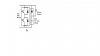
I am designing the 3-phase motor driver using 6 IGBT and 3 IR2110 drivers...


I want to use RCD snubber circuit like shown in the attached file...but I don't know how to calcullate R,C and D....my details for the supply and motor are----Vbus=230V ... R=5 ohm between each windings...
now I have checked the circuit with low voltages (~15V)... so I don't know other parameters...can u help me out??

how to know ripple voltage? how to calculate peak current?
Actually I found one website which can calculate parameters...but I am not able to crack...

Snubber Circuit Design Calculators
 

Attachments

  • snubber.jpg
    snubber.jpg
    21.1 KB · Views: 4,200
Actually I found one website which can calculate parameters...but I am not able to crack...

I cant make heads or tails of what they are using in their formulas either. But I dont tend to use much theoretical formulas anyway. Reality tends to put too many variables into the real equations and the theory stuff just seems to fall short in my opinion.:(

Most common VFD units just have a small snubber capacitor in parallel with the collector to emitter connections on the switching devices. The main capacitor bank you have on the supply rail will take up most of the spike energy that is created any way. The reversing diodes in the IGBT'S work like a high speed three phase bridge and simply transfer any major spike energy back to the main capacitor bank where it gets collected and then reused.

The actual snubbers on a 3 HP 230 volt IGBT type VFD unit are around .22 uf with ten ohms in series with the capacitor. The main capacitor bank typically has one or more small poly or ceramic capacitors in parallel with the big electrolytic. Or about 1/100 of the electrolytic values. They trim of the HF spikes the big electrolytic cant catch.
If your electrolytic bank was 1000 uf the snubber in parallel to it would be around a 10 uf poly capacitor. The snubber in parallel to the IGBT's would be around .22 uf with 10 ohms in series with them.

In case your wondering where I got the values I have a 3 HP VFD I converted over from three phase input to single phase. I changed the main capacitor bank over from two 470 uf to two 2200 uf capacitors and left the snubbers alone. I also put in a larger capacity input rectifier unit to handle the higher amps.

Over complicating a snubber system will cause more problems than it solves. ;)

Just some things to think about. :)
 
Thanks for your reply...
I do have centrifuge 5810 from eppendorf, in which this type of driver is used, but it has gone bad...now I am trying to make my own...
But I don't know the whether the motor is used is AC Induction or Ac synchronous or 3-phase brushless DC motor... the motor is covered , I can only see the 3 wires coming from inside...no details are there ...how to know which motor is there? I have checked the resistance between each winding is 5 ohm......
Can anyone help???
 
A three phase synchronous motor and a 3 phase brush less are the same for the most part. An induction motor is just a synchronous or brush less motor without the permanent magnets inside the rotor.
As long as the input voltage, frequency and current limits are respected any of the three will run off of a VFD system without problems.

If you short the three wires together that come from the motor and you feel drag while turning it its a synchronous or brush less type.
 
.

If you short the three wires together that come from the motor and you feel drag while turning it its a synchronous or brush less type.

Thanks for your handful replies...can you more clarify what kind of drag (and How)I should observe!! I am too dumb to understand that word because I am poor in motors...
If you give some practical test I will be very greatful to you!!!!!!
 
A three phase synchronous motor and a 3 phase brush less are the same for the most part. An induction motor is just a synchronous or brush less motor without the permanent magnets inside the rotor.
As long as the input voltage, frequency and current limits are respected any of the three will run off of a VFD system without problems.

If you short the three wires together that come from the motor and you feel drag while turning it its a synchronous or brush less type.


I want to solve this mystery for moving ahead...please tell me, is there any difference when you give pwm sequence for your igbt drive to drive 3-phase AC induction motor or BLDC or Synchronous AC motor???

I am confused because I don't know the motor is which type???
I heard that 120 degree phase diff. is necessary for AC synchronous??
I have designed pwm sequence as per pdf below..
https://www.electro-tech-online.com/custompdfs/2009/08/AN1916.pdf

help me out...
 
For peak current, you need to know the inductance you're driving. The you use the formula of the integral of the voltage divided by the inductance. For motors, the peak current can by as much as 5 - 7 times this value when starting or changing speed under a load. That fact is going to make any snubber non-ideal, and so you have to make a compromise. Perhaps you want to use the"high" value of current for you calculations, as that will be the most critical conditions. I'm trying to learn snubber circuits too, and so I'm interested in your project. If you need help with the equations, I might be ale to help. Also, the site you linked does the calculations for you. You can just plug and chug.

Typically, the equations get you a starting point, and you need to do alot of experimentation to optimise the design. Good luck!

Thanks ...I will be interested if you give me that equations...actually I have seen some, but I can't calculate the variable inside the eqns, so in vain...but anyway, if you help out then it would be better..:)
 
Which variables? They depend on your motor, as I already stated. If you can determine the inductance, you can calculate or approximate the peak current. Or you can measure it, hopefully with an oscilloscope. If you don't have access to a 'scope, then I don't know how you'll be able to optimise the circuit values.
 
Status
Not open for further replies.

Latest threads

New Articles From Microcontroller Tips

Back
Top