Hi guys,
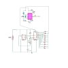
I have made a circuit using online sources and it doesnt work. What it should ! do, is move the servo from left to right then back to left in about 5 second pulsesThere are 3 parts. The first is a basic 555 timer which sends pulses to the second -
which is a cd4017, when clocked changes the resistance to the 3rd circuit
which is a 555 frequency circuit, which sends 1 - 2ms output to an rc servo.
The cd4017 is supposed to go from zero resistance , then gradually up to the full variable 2.7k ohm then gradually back down, automartically reseting.
When i try the pulsing 555 circuit, it works at about every 5 secs. Then i try the frequency circuit by itself and it works ( by changing the potentiometer 1 2.7k ) manually, i can get the servo to move from left to right. But when all is connected through the cd4017, it does nothing!
Any help would be appreciated
thanks very much
allan
(circuit attached)