Continue to Site

Welcome to our site!

Electro Tech is an online community (with over 170,000 members) who enjoy talking about and building electronic circuits, projects and gadgets. To participate you need to register. Registration is free. Click here to register now.

  • Welcome to our site! Electro Tech is an online community (with over 170,000 members) who enjoy talking about and building electronic circuits, projects and gadgets. To participate you need to register. Registration is free. Click here to register now.

Radio control by location

Status
Not open for further replies.
Off hand, I can imagine a GPS or solid state compass doing what you want. The GPS might be more complicated and less sensitive for the yaw (vertical) axis. Most compasses come with accelerometers in the same plastic IC, In most cases, you can ignore what you done't want. I have experience with the BMC156, MPU9250, and AK8963. The MPU9250 actually incorporates the AK8963 as I recall. It is the most complicated to deal with as it requires both SPI and I2C for the compass.

My personal favorite was the AK8963. It was easy (SPI), sensitive (more than the BMC), and gave fast response. Response time is under user control as you control the number of readings being averaged. My code is Assembly and for an enhanced mid-range PIC (probably the 16F1829). I found its datasheet easier to understand than the BMC's too.

I have attached a zipped file of the MP4. Not sure I can upload MP4 here. Hope it works.

John (aka JP or J1 :) )

EDIT: I had forgotten that I wrote a short review of those 3 chips:
Hi J,
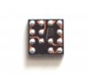
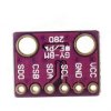
I'm now working on the Compass chip MPU9250.
I have the MPU-9250 Register Map and Descriptions Revision 1.4 and the AK8963 Data sheets, and as you say it's mighty complicated.

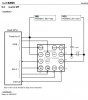
I think the best way to use it, is by using the FIFO, where each register must be pointed at, before READ. I don't think Oshonsoft can do this, and with previous modules, I READ each 8BIT address in quick succession.

Do you have any programs from when you used them, please.
C.
 
Hi,
I found a starter program for the Compass, written in that foreign language Arduino, but I'm sure some of you can read it.;)

EDIT: I'm a bit puzzled whether it uses Ic2 or SPI, I want to use SPI.
EDIT: I added an interesting note, attached.
EDIT: I may have made a mistake adding the INO and ZIP files below! If so, I found them from searches using 'MPU-9259 SPI', google and Github.
C.
 

Attachments

  • MPU9250_SPI.ino
    4.4 KB · Views: 246
  • mpu9250_spi.zip
    5.3 KB · Views: 245
  • MPU-9250 READ.txt
    6.6 KB · Views: 238
Last edited:
Hi,
On reading about the MPU-9250, I found that it needs both I2C and SPI to receive the DATA, so I'm now looking at the LSM303C which I hope will allow SPI only. Waiting for the ship to arrive.
C.
 
Hi,
I have tried different compass modules, and failing to be able to program them mainly because I2C, seems to be needed somewhere in the program, even if SPI is used.

I am now looking at the AK8963C module, which appears to be programmable to use SPI.

The price choices are a breakout board for app £25, a 3x3mm chip for £5/each or 5x BGA chips for £4. I have ordered the challenging BGA type as I will need a number of them. Here's a pic. (They're small:eek:)

I'm going to attempt to make breakout boards for them.

Would someone please look at the D/S and let me know how VID connection is PIN is connected please? Or if there is a schematic?

C
 

Attachments

  • BGA.jpg
    BGA.jpg
    88.1 KB · Views: 280
  • AK8963C SCH.jpg
    AK8963C SCH.jpg
    122.1 KB · Views: 268
It's just the CPU power voltage; if the CPU is 3.3V just connect VID and VDD to the same source.

It looks to be capable of running with lower voltage CPUs, so the SPI etc. can operate from a lower voltage than the main supply so the outputs do not exceed the CPU input voltage limits.
 
It's just the CPU power voltage; if the CPU is 3.3V just connect VID and VDD to the same source.

It looks to be capable of running with lower voltage CPUs, so the SPI etc. can operate from a lower voltage than the main supply so the outputs do not exceed the CPU input voltage limits.
Hi R,
Thanks for the clarification.
C.
 
Hi,
Hi,
Finding a compass module has been a bit of a puzzle. It needs to be SPI configured, which isn't always straight forward.
I found a likely one, used in iphones: AK8963C, but the breakout board, is quite expensive, so I decided to try to make my own.
Here is my breakout board:
I've got it working, now I need to get sensible compass READings out of it, here: https://www.electro-tech-online.com/threads/twos-compliment-in-oshonsoft.153076/

C.
 

Attachments

  • AK8963 Break out.jpg
    AK8963 Break out.jpg
    279.2 KB · Views: 253
Hi,
Here's a progress update:
Previously, I used a PCB with an 18LF4520 PIC for testing each of the modules. 5110 Nokia screen, BMP280 as Altimeter, AK8963C Compass, HC-12 Radio.

Both TX and RX are the same, with variations e,g, SERVOs on the RX (Mainly the program)

Due to low memory of the 18LF4520, and the conflict timings for the RX SERVOS, I now have a PCB with two PICs. 18F4620 and 18LF2520.

I now have all of the modules connected to the PCB. I read the outputs of the modules, via an HC-12 on the PCB and another connected via a serial USB to a computer screen.

All of the modules are attached along with a circuit SCH and PCB.

Using the latest program:
The Compass and altimeter are working. I'm working on the GPS section now.

As always any help appreciated.
C.
 

Attachments

  • 5110 Pinouts.jpg
    5110 Pinouts.jpg
    23.2 KB · Views: 286
  • BMP280 Barometer module.jpg
    BMP280 Barometer module.jpg
    7.7 KB · Views: 246
  • NEO-M8N-GPS APM.jpg
    NEO-M8N-GPS APM.jpg
    235.3 KB · Views: 273
  • HC-12.jpg
    HC-12.jpg
    117.9 KB · Views: 261
  • AK8963C BREAK OUT BOARD.jpg
    AK8963C BREAK OUT BOARD.jpg
    186.2 KB · Views: 239
  • 2XPIC PCB.jpg
    2XPIC PCB.jpg
    199 KB · Views: 261
  • 2XPIC SCH.jpg
    2XPIC SCH.jpg
    198.9 KB · Views: 266
  • 18F4620 8MHz 5110 GPS BMP280 AK8963C HC12 151218 0900 TEST.txt
    16.2 KB · Views: 252
Last edited:
Hi,
I've just updated the program file #50.
The Compass, Altimeter are working, and the GPS now compiles.
C.
 
Hi,
Here's the latest program.

I've copied and pasted the 5110 screen and PMP280 sections from previous working programs into this one.

The 5110 screen SPI from the PIC is working with a logic analyser.

Here is a note from J:
At least the compass raw values are again in wrong order.
Why are you using different loop counters, when one is enough, for example i
The same with buffer array, maybe there are more.

Hi J,
I'll re-order the compass RAW values, and from now on, no more copying and pasting, as this is how I made the mistake.
C.
 
Last edited:
Hi J,
I've removed the multiple 'counters' and 'arrays' and it looks like it's working as before, with GPS HC-12 and compass.

Are the compass RAW values still in the wrong order? It looks as though the compass is working.

EDITED:
I've found a missing section from the BMP280, so just looking at it.

C. Happy New Year.
 

Attachments

  • 010119 LOGIC.jpg
    010119 LOGIC.jpg
    188.7 KB · Views: 253
  • 18F4620 8MHz XTL RX 5110 GPS BMP280 AK8963C HC-12 010119 1100.bas
    25 KB · Views: 222
Last edited:
Hi,
All of the modules are 'talking' to the PIC apart from the 5110 screen.

I'm pretty sure the tracks are ok.

While testing, I found that none of the SCREEN 'switches' that is CS, MODE or RESET PINs are switching.

I've just tried a simple switching test, where all of the screen PINs are switched, including the SPI, also RLED and a PIN from the radio. Aging all switch apart from the SCREEN switches.

EDIT: Later I tried switching ON/OFF all of the PORTS and as before the 3x PINs aren't switching.

It simulates ok.

Any ideas?

C.
 

Attachments

  • 18F4620 8MHz XTL simple on off test.bas
    3 KB · Views: 238
How did you get CS working?
Have you tried: toggle RC0, RC1
or better with toggle LATC. 0, LATC. 1
 
How did you get CS working?
Have you tried: toggle RC0, RC1
or better with toggle LATC. 0, LATC. 1
Hi J,

CS was working when I re-tested, so maybe I made an error 1st time.

Next I tried ALL LAT ON/OFF: no good.
Then I tried a second PCB: no good.
Then I commented out all of the header (I think it's called that?) and the both ON/OFF, so the problem is somewhere in the header.

This works (Note commented out)
C.
 

Attachments

  • 18F4620 8MHz XTL simple on off LAT test.bas
    2.8 KB · Views: 208
Hi,
It appears to be the TIMER set-up, that's causing the LATE.0 and LATE.1 problem.
C.
''''''''''''''''''''''''''''''''''''''''''''''''''''''''''''''''''''''''''''''''''''''''''''''''''''''''''''''''''''''''''''''''''''''''''''''''''''''''''''''''''''''''''
'T1CON = %00111101 '1:8 -> Timer1 clock = 1MHz'<<<<<<<<<<<<<<<<<<<<<<<<<
'T2CON = 0 '<<<<<<<<<<<<<<<<<<<<<<<<<<<<<<<<<<<<<<<<<<<<<<<<<<<<<<<<<<<<<<<
'T3CON = 0 '<<<<<<<<<<<<<<<<<<<<<<<<<<<<<<<<<<<<<<<<<<<<<<<<<<<<<<<<<<<<<<<<<
'PIR1 = 0
'PIR2 = 0
'PIE1 = 0
'PIE2 = 0
'PIE1.RCIE = 1 'rxd Intr , used for GPS serial input work[[[CHECK IF STILL NEEDED]]]
'IPR1 = 0
'IPR2 = 0
'IPR1.TMR1IP = 1
'''''''''''''''''''''''''''''''''''''''''''''''''''''''''''''''''''''''''''''''''''''''''''''''''''''''''''''''''''''''''''''''''''''''''''''''''''''''''''''''''''''''''
 
From the d/s:
When Timer1 is enabled, the RC1/T1OSI and RC0/
T1OSO/T13CKI pins become inputs. This means the
values of TRISC<1:0> are ignored and the pins are
read as ‘0’.
 
Status
Not open for further replies.

Latest threads

New Articles From Microcontroller Tips

Back
Top