Continue to Site

Welcome to our site!

Electro Tech is an online community (with over 170,000 members) who enjoy talking about and building electronic circuits, projects and gadgets. To participate you need to register. Registration is free. Click here to register now.

  • Welcome to our site! Electro Tech is an online community (with over 170,000 members) who enjoy talking about and building electronic circuits, projects and gadgets. To participate you need to register. Registration is free. Click here to register now.

Remote Control By Location Part 2

camerart

Well-Known Member
Hi,
About 4 years ago, I got the idea for a little project. I wanted to control mechanical items, in this case a Tricopter, by sending a location, which means Altitude, LAT and LONG plus other things. LAT LONG etc doesn't need to be used, if for eaxample I wanted to control 'say' a robot, where some other control would be sent.

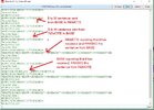
Anyway 4 years later I/plus lots of assistance from forums etc, have got it going. When I say that, I mean the Transmitter and Receiver, can send between them DATA such as mentioned, inculding peripherals: Radio, GPS, Altimeter, compass, incremental encoder and Joysticks.


Thanks, for all of the help.
Camerart.
 
Last edited:
Hi,
Update:
All peripherals on both BASE and REMOTE PCBs are working including the screen.
Today I/we got then both to 'talk' to each other.
C
 

Attachments

  • BORI_ROBI.jpg
    BORI_ROBI.jpg
    206.3 KB · Views: 247
Hi,
Here's a general question, as a full question would be too complicated!

In the main program, (which a version can be seen here and in various updated states) I use a PARSE system on DATA that is input to the RX of an 18F46K20 PIC, this works well.
I want to change the input pin to one of these peripherals to another pin, to avoid RC clashes. This pin would use HSERIN.
What I want to know is: will data from different sources, be parsed as before?
I realise that this is a vague question, but I'm trying to avoid a long thread.
Cheers, Camerart.
Vague answer to a vague question - yes.
 
HSERIN only works with the one and only one hardware EUSART in that PIC chip, as far as I understand.
You could try a software serial in "SERIN" to read data on another pin, but software serial has its issues. Software uart code can take more CPU power, as it is the CPU that has to assemble the bits into a byte, instead of a hardware UART. Also, there is no easy way to reset a read as in resetting a UART, so a read can lock up unless you enable SERIN_TIMEOUT_REG and SERIN_TIMEOUT_BIT. That allows the reading loop of the software "uart" to check if it is to abort the read or not. This timeout bit is usually tied to a timer and its "timer complete" flag.
There are also no hardware status bits you can check with a software read routine. With software you cannot tell if data is in progress of receive. You also cannot trigger an interrupt when read is complete when using software read routines.
Hi N and S,
In #4 I said HSERIN, but I meant SERIN.

To clarify:
I'm using the RX pin for receiving DATA, via radio, plus a GPS through a switch, into the same PIN.

Because of this, I now want to use another PIN with SERIN, to READ the GPS.
I've done this before, but I'm sure it was on the RX PIN, I can check my history files.

If the issues outlined by S are a problem, there is another PIC on the PCB, with a spare RX PIN, that I could use, would this be better?
C
 
In Oshonsoft, SERIN can be used on any digital pin that is defined as input. In most cases, SERIN is relatively accurate at lower baud rates, up to 9600 baud or perhaps a bit more.
Always watch out for any receive lockup. The only way to terminate a SERIN is with the timeout register and timeout bit. You can use any port register and trigger a cancel by setting a bit, instead of using a timer to time out a read command.
SERIN cannot detect framing errors, overflows or other errors in the structure of the serial data stream.
 
Hi,
As there are 2x PICs on the PCB, I have now got the RX on PIC2 to work, instead of SERIN on PIC1.
Thanks.
C
 
Hi Happy New Year,
Update: This project is still plodding on, with all of the peripherals working on all 4x programs.
My mate is tidying up each program, with Procedures, Functions and Includes, while I try to get the REMOTE SERVO/MOTOR outlets to work.
Cheers, Camerart.
 
Hi,
Update: The SERVO/MOTOR control section is working.
Next I'm working improved SPI CODE.
C
 
First: my mate has written CODE for the SPI (between PICs) and I ought to see if i can get this going.

Be sure to post both sides of the code for that (master and slave). SPI between two pics can be surprisingly complicated to get right, especially since the master never really knows when it's ok to initiate a transaction.

Unless you have extra hardware involved it's difficult to sync the two sides, and to know when one message ends and another begins if the two sides ever get out of sync.
Hi M,
The SPI is between only MASTER and SLAVE of each PCB (base remote) even so it is still complicated, and as mentioned still in progress.

The GPS/SERVO CODE you posted, now needs the GPS BYTES to be READ. I tried it with SEROUT, but as you mentioned uses to long time, so it glitches the SERVOs.
C
 
If the servos have priority you may be stuck restructuring things so that the servos are driven from a high-priority interrupt. Everything else would be either low-priority or main line code.
 
If the servos have priority you may be stuck restructuring things so that the servos are driven from a high-priority interrupt. Everything else would be either low-priority or main line code.
Hi T,
It's probably best that I go back to the thread (link in #14)
C
 
If the servos have priority you may be stuck restructuring things so that the servos are driven from a high-priority interrupt. Everything else would be either low-priority or main line code.
As stated in the other thread, I deliberately stayed clear of prioritized interrupt because I don't know how they work in Oshonsoft. Plus the longest interrupt (Guestimate -measured once at 30) is less than 50 clock cycles so nothing should get missed.

The servo interrupt is not critical as the pulses are generated by hardware and as long as the ISR is serviced within ½mS (4000 clock cycles) then all will be well. Same with the UART (1mS) and the (pseudo) hardware serial out (104uS). Note, even 104uS is 816 clock cycles.

Mike.
 
Hi,
An update:
'Everything' is now working, but most of it needs re-looking at.
At the moment me and a mate of mine are working on the SPI section between the PICs and peripherals, (Programs 1 and 2 BASE) which as said, is working, but needs tidying.
Once all's fine, I'll transfer them to (Progs 3 and 4 REMOTE)
C.
 
Hi,
I'm a bit stuck!
Here are programs 1 and 2 from the BASE.:

The SLAVE 18F4431 reads the GPS, and the Incremental encoder, and sends it via SPI to the MASTER 18F46K20. when monitoring the MASTER using a computer terminal, I can see the SPI working, but then it stops, and recovers if I reset the SLAVE, until the next time?

The MASTER reads the ALT, COMP, JOYSTICKS ok, and the screen is working, however, even though the RX is receiving simulated DATA via the radio, and was working a year ago, is not working now.

Any ideas welcome. (I may have missed something!, I'll also post this on AAC, as they have contributed to it)
Cheers, C.
 

Attachments

  • 18F46K20 32MHz XTL PCB_8 MASTER S2M_ACK 130723 1830.bas
    41.9 KB · Views: 126
  • 18F4431 32MHz XTL SLAVE S2M_ACK after BYTE 030723 1500.bas
    26.6 KB · Views: 120
Last edited:
Hi,
An update:
Still working away it this project, and at the moment there is a problem with the GPS RX on the PIC.
I've had a long thread on AAC, about BAUD rates.
for some reason, I can't change the BAUD rate on the PIC, and the GPS data can only be read when the GPS is set to 38400 BAUD, even though the PIC has been set to 9600 or 2400.
(Note: I'm going to ask a general BAUD question on a new thread!)
C.
 

Latest threads

New Articles From Microcontroller Tips

Back
Top