Continue to Site

Welcome to our site!

Electro Tech is an online community (with over 170,000 members) who enjoy talking about and building electronic circuits, projects and gadgets. To participate you need to register. Registration is free. Click here to register now.

  • Welcome to our site! Electro Tech is an online community (with over 170,000 members) who enjoy talking about and building electronic circuits, projects and gadgets. To participate you need to register. Registration is free. Click here to register now.

Radio control by location

Status
Not open for further replies.
Hi,
I've have been working on this unfinished program:

I now find that I need 6x ANALOG IN PINS and 6x PWM OUT PINS. (Poor planning:(
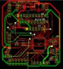
) on the TX and RX PCBs

I've searched using Microchips MAPS and found the 18LF6622 PIC

Does the 18LF6622 PIC look as though it will have 6x ANALOGUE INPUTs 6x PWM OUTPUTS and has enough memory for the program 'not quite finished', attached? In other words future proof'ish
C
 

Attachments

  • 18LF4520 HMC5983 110318 1400 READ XZY 6bytes.bas
    17.4 KB · Views: 227
Last edited:
Off hand, I can imagine a GPS or solid state compass doing what you want. The GPS might be more complicated and less sensitive for the yaw (vertical) axis. Most compasses come with accelerometers in the same plastic IC, In most cases, you can ignore what you done't want. I have experience with the BMC156, MPU9250, and AK8963. The MPU9250 actually incorporates the AK8963 as I recall. It is the most complicated to deal with as it requires both SPI and I2C for the compass.

My personal favorite was the AK8963. It was easy (SPI), sensitive (more than the BMC), and gave fast response. Response time is under user control as you control the number of readings being averaged. My code is Assembly and for an enhanced mid-range PIC (probably the 16F1829). I found its datasheet easier to understand than the BMC's too.

I have attached a zipped file of the MP4. Not sure I can upload MP4 here. Hope it works.

John (aka JP or J1 :) )

EDIT: I had forgotten that I wrote a short review of those 3 chips:
Hi JP,
I've tried and failed to get 2 or three types of compass to work, but even though I did get some of them to 'try' I couldn't get one working properly.
I've got some MPU-9255 modules on order, let's see how I get on with those.
C.
 
Hi,
I've made a start with new PCBs, here's the schematic for the RX, which I'm trying first.
Any comments or corrections welcome.

EDIT 'I've found some errors, I'll repost once redrawn.

C.
 
Last edited:
Hi,
Here's the schematic and PCB:

Any comments or corrections welcome.

EDIT: Updated

C.
 

Attachments

  • 18LF4431 RX PCB (2).jpg
    18LF4431 RX PCB (2).jpg
    198.3 KB · Views: 245
  • 18LF4431 RX SCH.jpg
    18LF4431 RX SCH.jpg
    187.6 KB · Views: 270
Last edited:
Hi,
I have just realised that the PIC I've chosen for the RX PCB 18LF4431, may not have enough memories etc, as it's less than the TX choice of 18LF4520:(

EDIT: ERROR,I had the PIC numbers reversed, NOW CORRECTED. It is the 18LF4431 that doesn't have enough memory for the full program. As I've spent some time on the PCB, I'll carry on with some tests.

C.
 

Attachments

  • 18LF4520 5110 GPS BMP280 HC12 150418 1100.bas
    18.1 KB · Views: 230
  • Memory.jpg
    Memory.jpg
    199.1 KB · Views: 248
Last edited:
Hi,

I've updated the SCH and PCB on #25 (small changes)

Here's a test program:
The PIC is powered, and programs ok, I also tried verify, again OK.
The YLED is soldered onto the PCB, but doesn't flash as expected, any ideas?

I don't see CONFIG1L when I look at 'config bits' in the Oshonsoft simulator, am I misunderstanding something?
C
 

Attachments

  • TEST.bas
    1.4 KB · Views: 245
  • CONFIG1L.jpg
    CONFIG1L.jpg
    183 KB · Views: 246
Last edited:
Does the red LED flash? It should, along with the yellow. If neither LED is flashing, then something wrong with the configuration. Based on your schematic, both yled and rled should flash ok based on that simple code (from what I can see). Diagnose if either LED is working first....
Other than that, can't help much, I don't work with the 18F series of chips
Hi S,
I tried another forum for any answers, and changed the CONFIG settings, which has now got one LED flashing, so the PIC is working.
I'm now looking for why the second one doeasn't work, perhaps another CONFIG setting?
C.
 
Hi,
I got some help from AAC, to set up the CONFIG for the 19LF4431.
Here is the latest test program, where I'm trying to combine previous programs to see how the PIC memory fares:
At the moment I've tested the HC-12 as a TX and it appears to be working, later I'll set it correctly to RX.
The memory is getting pretty full!
C.
 

Attachments

  • 18LF4431 HC-12 BMP280 RX 080518 1400.bas
    14.1 KB · Views: 241
Hi,
When I did my test TX to RX using an 18LF2520 as RX, these LOOPs were working, they're almost working using the 18LF4431 as RX, can anyone see why they aren't fully working?

The TX, 19LF4520 send this:
main:
If button = 1 Then 'BUTTON NOT PRESSED
rled = 0
yled = 1
Hserout "$0", CrLf
Endif
If button = 0 Then 'BUTTON PRESSED
rled = 1
yled = 0
Hserout "$1", CrLf
Endif
Goto main

The RX 18LF4431 LOOP is here:
main:

rxi = 0
If RCSTA.OERR = 1 Then 'RCSTA BIT1-if over run error then flush RXD buffer
RCSTA.CREN = 0
RCSTA.CREN = 1
char = RCREG
PIR1.RCIF = 0
Endif

sync1: 'wait for a '$' start of string
Hserout "NOT£", CrLf
If PIR1.RCIF = 0 Then Goto sync1
char = RCREG

If char <> 0x24 Then Goto sync1 '$'
str1(1) = char 'STR1 ARRAY
rxi = 2

get_msg: 'read and save
If PIR1.RCIF = 0 Then Goto get_msg
char = RCREG
str1(rxi) = char 'STR1 ARRAY
rxi = rxi + 1

If char = 0x0a Or char = 0x3f Then Goto decode 'tests for either LF or ?
Goto get_msg

decode:
If str1(2) = "0" Then
Hserout "4431 WLED OFF YLED ON: ", CrLf
wled = 0
yled = 1
Endif

If str1(2) = "1" Then
Hserout "4431 WLED ON YLED OFF: ", CrLf
wled = 1
yled = 0
Endif

Goto main

There is an element of TX in both LOOPs, and both are 'seen' by a terminal.
If I switch on the TX only, the terminal shows either $0 or $1, as expected, and was working before.

If I switch on the RX only, the terminal shows NOTE£ repeatedly.

If I switch on TX and RX the RX doesn't appear to 'see' the $.

C.
 
Hi, [REMOTE PIC only, not BASE]

Trying to get the REMOTE PIC program to work , I connected a SERIAL TERMINAL (1) to the RX PIN instead of the HC-12. The TX PIN is still connected to the HC-12. A second TERMINAL (2) is receiving any output from the TX.

Adding lines into the PIC program e,g, WAITMS and HSEROUT trying to find out where the problem lies, and kind of narrowed it down to the :If char <> 0x24 Then Goto sync1 '$' line or something to do with it.

[The REMOTE program always works in the Oshonsoft SIM]

Today it started to work ok, so I started removing the lines I had added, so see where it starts to fail, but it doesn't. So now the program is back to it's original form and working ok.

Next I'm going to remove TERMINAL (1) and try the HC-12 again.

Any ideas?
C.
 
Hi,
I've now tried it as it was originally, with the HC-12 and now it's working.
It's difficult to trust it, while I don't know what the problem is!
C.
 
Last edited:
Hi, [Receiver PCB]
Here's the program so far. It receives the 6x SERVO times then outputs to 6x SERVOS. (It's a test, and not proved yet)

I need to set the TMR0 INTERRUPT to 20MS.
C.
 

Attachments

  • New Text Document.txt
    5.8 KB · Views: 236
Hi,
The TIMER program in #34 has WAITs, here is another using TMR0 instead, which is how it should be done.

It's a test program, and has a lot of lines that need removing as I get things working.
It has a WAITUS14, which will be changed to TMR0 later.
The radio module is working.

C.
 

Attachments

  • 18LF4431 SERVO 250618 1100.txt
    10.6 KB · Views: 221
Hi,
I'm now using an 18F46K20 for the main program, with an 18LF2520 dedicated to SERVO control on one PCB.

The program still needs the compass module checking, which I'll do next, and will mean that all of the necessary modules will be working.

I've just got the 18F46K20 to READ an NMEA sentence sent via an HC-12 radio and a TERMINAL (Teraterm), then do a little calculation and TRANSMIT the sentence plus the result back to the terminal.
Here is the result:

C.
 

Attachments

  • NMEA.jpg
    NMEA.jpg
    198.2 KB · Views: 241
Last edited:
Hi,
I'm getting odd results from HSEROUT!

As #36, NMEA sentences are generated in a Terminal and sent to the PIC HSERIN.
After process, they are sent back to the Terminal and can be read on a screen.
Here are various results, with # for Ascii in different settings.
'NMEA' shows the correct result, but in 'NMEA no #' the same setting shows incorrect result
Any ideas please?
C
 

Attachments

  • NMEA #.jpg
    NMEA #.jpg
    55.5 KB · Views: 233
  • NMEA no#.jpg
    NMEA no#.jpg
    41.8 KB · Views: 237
  • NMEA.jpg
    NMEA.jpg
    74.4 KB · Views: 243
Last edited:
What is the type of strtim?

# converts a numeric value ( byte, word, single) to a string.
Not the other way.
For example i = 0xff
#i = "255"
 
Which program version are you now testing?
They are spread into different threads and it is quite confusing to follow.
 
Last edited:
Which program version are you now testing?
They are spread into different threads and it is quite confusing to follow.
Hi J,
Regarding my question at #37, I think the results will be a number with 2 or 3 after the decimal point. I'm not actually sure what form they will be, so I'll withdraw the question till later, when I have developed the program farther.

So far I've made separate programs, for testing each module, and indeed it is confusing.

I'm now adding the last module (Compass) Here is the program:

I'll post all new programs here to keep it less confusing. Always use the last date program, as I change the date when any lines or BITs are updated, as I learn them.
C.
 

Attachments

  • 18LF4620 32Mhz RX 2XPIC COMPASS HC-12 130918 1030.bas
    17.1 KB · Views: 224
Status
Not open for further replies.

Latest threads

New Articles From Microcontroller Tips

Back
Top