Chris in Mesa
New Member
I hope someone can help me out. I'm attempting to build my first circuit (the incandescent dimmer circuit from the microchip site):
https://www.electro-tech-online.com/custompdfs/2009/09/91094A.pdf
I was putting together a parts list and when I came to the resistors, I didn't know the wattage that I needed - only the Ohms are listed. If anyone can help me figure out the wattage of the resistors, it would help a lot.
I searched the forums and came across another dimmer design. Does anyone with experience have an opinion as to whether one schematic is “better” than the other?
https://www.electro-tech-online.com/threads/light-dimmer-controlled-by-pic.88654/
Does anyone know if I can just use a generic IR transmitter / receiver pair instead of the ones listed?
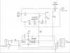
On the diagram of the receiver (see attached), there are several places (near the lower left for instance) where the lines are terminated with an arrow. Where does this connection "really" go? For example, the arrow to the left of the 47 mfd capacitor, and the arrow on the number "2" of the IR receiver [GP1UD261RK]. I’ll take an answer or a link, or an hint as to where to find that information out for myself.
One more question (for now). What do you think the jumpers are for?
So basically, I will take any help that the community can give. I have tried to do my homework before submitting.
Thanks a bunch! Chris
https://www.electro-tech-online.com/custompdfs/2009/09/91094A.pdf
I was putting together a parts list and when I came to the resistors, I didn't know the wattage that I needed - only the Ohms are listed. If anyone can help me figure out the wattage of the resistors, it would help a lot.
I searched the forums and came across another dimmer design. Does anyone with experience have an opinion as to whether one schematic is “better” than the other?
https://www.electro-tech-online.com/threads/light-dimmer-controlled-by-pic.88654/
Does anyone know if I can just use a generic IR transmitter / receiver pair instead of the ones listed?
On the diagram of the receiver (see attached), there are several places (near the lower left for instance) where the lines are terminated with an arrow. Where does this connection "really" go? For example, the arrow to the left of the 47 mfd capacitor, and the arrow on the number "2" of the IR receiver [GP1UD261RK]. I’ll take an answer or a link, or an hint as to where to find that information out for myself.
One more question (for now). What do you think the jumpers are for?
So basically, I will take any help that the community can give. I have tried to do my homework before submitting.
Thanks a bunch! Chris
") I did go ahead and order a 38kHz substitution pair from them anyway.
I did go ahead and order a 38kHz substitution pair from them anyway.