ADWSystems
Member
I purchased a Adafruit PowerBoost 1000C for a project I'm working on. It provides lots of options. The ones I'm using for the shared output voltage and the 5V output.
In block diagram terms, I have the PowerBoost connected to a series of items that can take 3.0-4.4V so those are connected to the shared votage out (which is either from the USB charger or the battery). There is a sensor that requires 4V minimum, so that is connected to the 5V output.
My intention was to use a SPST switch, then I found the 5V output has a different method to turn it off (connect EN to GND), so I changed to a DPST switch. Then found I goofed as shutting off 5V is making a connection as is supplying the shared voltage to the low voltage modules. So a DPST switch won't work as the power is supplied in opposite conditions (one N.O. and one N.C.). So I switched to a (awful and ugly) DPDT slide switch I had on hand. The problem with the switch is it will be prone to getting turned on and the unit is tossed into a bag.
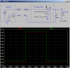
The is the original/current wiring:

What I would like to do is to get back to a SPST switch (or at least a SPDT) switch. I have a lot of options that aren't prone to getting turned on accidentally.
Based on a recent conversation about FETs, I was thinking something along the lines of:

The design goal is to have zero current draw when the switch is OFF and to have minimal (almost none) to enable the boost circuit when the switch is ON. I was trying to disconnect EN from GND when the gate is connected to a positive voltage. I know from the recent discussion on N-FETs, that a N channel FET is not going to work when wired like above.
I know:
1) Source is GND is 0V
2) EN is connected by a 200K resistor to the battery
2) The gate will vary from floating (bad thing?) when unpowered to 3.0-4.4V when turned on.
LiPo power varies from the battery voltage to the USB charging voltage (should be 3.0-4.4V). It is less than 3.0 the power circuit will not enable and produce 5V.
Is 3.0V Vgs enough to enable the FET fully?
Would this work? Other options?
In block diagram terms, I have the PowerBoost connected to a series of items that can take 3.0-4.4V so those are connected to the shared votage out (which is either from the USB charger or the battery). There is a sensor that requires 4V minimum, so that is connected to the 5V output.
My intention was to use a SPST switch, then I found the 5V output has a different method to turn it off (connect EN to GND), so I changed to a DPST switch. Then found I goofed as shutting off 5V is making a connection as is supplying the shared voltage to the low voltage modules. So a DPST switch won't work as the power is supplied in opposite conditions (one N.O. and one N.C.). So I switched to a (awful and ugly) DPDT slide switch I had on hand. The problem with the switch is it will be prone to getting turned on and the unit is tossed into a bag.
The is the original/current wiring:
What I would like to do is to get back to a SPST switch (or at least a SPDT) switch. I have a lot of options that aren't prone to getting turned on accidentally.
Based on a recent conversation about FETs, I was thinking something along the lines of:
The design goal is to have zero current draw when the switch is OFF and to have minimal (almost none) to enable the boost circuit when the switch is ON. I was trying to disconnect EN from GND when the gate is connected to a positive voltage. I know from the recent discussion on N-FETs, that a N channel FET is not going to work when wired like above.
I know:
1) Source is GND is 0V
2) EN is connected by a 200K resistor to the battery
2) The gate will vary from floating (bad thing?) when unpowered to 3.0-4.4V when turned on.
LiPo power varies from the battery voltage to the USB charging voltage (should be 3.0-4.4V). It is less than 3.0 the power circuit will not enable and produce 5V.
Is 3.0V Vgs enough to enable the FET fully?
Would this work? Other options?