Continue to Site

Welcome to our site!

Electro Tech is an online community (with over 170,000 members) who enjoy talking about and building electronic circuits, projects and gadgets. To participate you need to register. Registration is free. Click here to register now.

  • Welcome to our site! Electro Tech is an online community (with over 170,000 members) who enjoy talking about and building electronic circuits, projects and gadgets. To participate you need to register. Registration is free. Click here to register now.

Queries about DC to AC Inverters

Status
Not open for further replies.
inverter

here is the circuit please check out that whats wrong.
 

Attachments

  • untitled.JPG
    untitled.JPG
    25.4 KB · Views: 255
The circuit looks good.
You forgot to show transistor numbers, the power rating of the transformer, the current rating of the 12V supply and how the 4047 is wired.

It is very similar to my 100w inverter design:
 

Attachments

  • 100W inverter.GIF
    100W inverter.GIF
    14.9 KB · Views: 249
you could do it like that...

Or forget about using a centre-tapped transformer and use one that isn't (if you have a centre-tapped one then never mind).

with yr 12V have your DC-link capacitance in the form of two seriesed up with the mid-point the virtual-earth the the transformer primary winding goes between the phase output of the power-leg and the virtual-earth

PWM the top-switch with a duty to synth a sine-wave positive cycle and PWM the bottom switch to synth a sine-wave negative cycle.

With control loop closed around a re-scaled version of the outputted 220V (50Hz?)
 
inverter

here is the wired circuit of CD4047. I used the transformer 10v-0v-10v 50A primery and 3.6A 220v secondry.IS this transformer right.inv.JPG
 
You made the 500W inverter project from another site. I fixed it, because its oscillator had the wrong value resistor and capacitor.
I also fixed its transistors circuit.

Your transformer is good for 500W output but you forgot to show which transistors you used. Your transistors will limit the output power to about 100W or less.

Your power transistors do not have a resistor from base to emitter to turn them off.
 

Attachments

  • inverter oscillator.PNG
    inverter oscillator.PNG
    110.6 KB · Views: 235
Just going into more detail about what Styx is saying.

I would use a ferrite core transformer connected to a full h-bridge connected to a PWM working at about 40kHz and put a low pass filter on the output to only allow the 50Hz or 60Hz signal to pass.

A pure sinewave inverter isn't that complected, all it is is a class-D amplifier working at an extremely low frequency; it's a lot easier to build than a class-D audio amplifier.

Also not only will it give a good sinewave, it'll be more efficient and more compact than a modified sinewave inverter.

Google for class amplifier if you want more information.
 
I had red in a book name(modern inverter and converter circuits) that the transformer used in 12v inverter should be 20v center taped.
I dont know that why it should not 24v center taped.
 
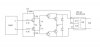
Supposed, 5000 Watt Inverter???????????

Here is a PDF File that a guy sent me.

He was wanting my advice in making this 5000 Watt Inverter that he found this on the Internet Somewhere.

I Added the "WHAT A JOKE" to the name of the PDF, Just so no one else woul take this seriously.

**broken link removed**

Even at Instanous PEAK POWER, I Doubt it could obtain that wattage.

audioguru, What do you Think?
 
OK thats right but i onley want to know that why some companies which i had absorved that they use 20v (center taped) to 220v transformer. Is it Right?
 
Hi Gary,
That "5000W" inverter came from this Japanese guy:
https://hobby_elec.piclist.com/e_ckt8.htm
It has a whopping 3A from the 12V battery so its output is only 36W.
I think it is capable of producing an output of 50W. Then use 100 of them

Hi Dimper,
The transistors in an inverter have a voltage loss of about 1.5V. But a "12V" car battery is 13.8V or 14.4V when fully charged. So the extra increase in output voltage when a 10V transformer is used is not necessary.
 
THNKS FOR HELP.
Can u please send me the current rating table of Standard Wire Gauge(SWG) used in inverter transformers.
 
Hello all,
My requirement is quite different. I intend to build a 1.5kVA inverter that will draw less current from the battery when few loads are connected (i.e trying to avoid running down the battery when just a 40W bulb is connected) and progressively draw more current from the batter as the load increases.

This in my view will make the inverter more efficient. Any ideas pls

Regards
 
Status
Not open for further replies.

Latest threads

Back
Top