Electro Tech is an online community (with over 170,000 members) who enjoy talking about and building electronic circuits, projects and gadgets. To participate you need to register. Registration is free. Click here to register now.
Welcome to our site! Electro Tech is an online community (with over 170,000 members) who enjoy talking about and building electronic circuits, projects and gadgets. To participate you need to register. Registration is free. Click here to register now.
I want to design a SSB modulator using the phasing method.
Can you guys please introduce me a good quadrature 90 degrees oscillator chip or circuit for the carrier osscilator section?
The very simple:
Just use an R-L and an R-C network. One gives a 45 degree phase lead, the other gives a 45 degree phase. Hence 90 degree shift between the two.
However this will be tricky to set up, will probably drift, and will only work over a small frequency range.
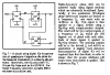
A standard approach:
Uses three D-type flip-flops to divide an oscillator which is running at four times the required frequency.
Works over a wide frequency range with an accurate 90 degree phase shift between outputs.
The super-duper fancy and expensive way:
Use two Direct Digital Synthesiser (DDS) chips driven by a common oscillator.
The control words sent to each chip from the microcontroller are the same except for the phase bits.
Set the phase bits to zero for one chip and 90 degrees for the other chip.
Result is two very stable signals phase shifted by 90 degrees.
So, for the "standard approach" you described, one would get this, no?
**broken link removed**
But how would you get two signals 90° out of phase out of that? (I have no doubt that it can be done, just couldn't figure out this particular puzzle.)
Hmm, maybe you don't need that bottom wave, since you said 4 times the frequency, but since you're using 3 FFs, I wonder what the third one is doing.
surely a Wien Bridge Oscillator can set up the in phase and feed this though an integrator to get the Q phase. From my days at school, when differentiating Sine -> Cos and Cos -> negative Sine. This keeps all the waveforms as sine/cos and not square
This site uses cookies to help personalise content, tailor your experience and to keep you logged in if you register.
By continuing to use this site, you are consenting to our use of cookies.