Continue to Site

Welcome to our site!

Electro Tech is an online community (with over 170,000 members) who enjoy talking about and building electronic circuits, projects and gadgets. To participate you need to register. Registration is free. Click here to register now.

  • Welcome to our site! Electro Tech is an online community (with over 170,000 members) who enjoy talking about and building electronic circuits, projects and gadgets. To participate you need to register. Registration is free. Click here to register now.

Qns on DC Power Supply

Status
Not open for further replies.

adrian22

New Member
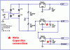
Input +15V AC==========> output +15V, -15V, -5V DC

we noe we can place a bridge FW & a capacitor to get a dc +15V

but how can we suppy +15V & -15V in ther same time? :roll:

so with the -15V we can so regulator LM 7915 & LM 7905 the have a output of -15V & -5V.

Result +15V, -15V, -5V DC

pls help thx u


Regards
Adrian
 

Attachments

  • _15v.jpg
    288.3 KB · Views: 1,420
You need a 15-0-15 transformer, followed by a bridge rectifier, this will give about +22V and -22V. If you want +15 and -15 you would need a transformer about 10-0-10, or (preferably) use regulators to provide smooth stabilised supply rails.

But it depends what the supply is feeding!.
 
Over all circult

Sp a transformer itself has a +15V, 0V and -15V. by drinving across the bridge rectifier the voltage will drop 1.4V.

As a result, we can't use a transformer supplying +15V, 0V and -15V we must use a +22, 0V and -15V?

But we r told & given only 15V, 0V and -15V.
So how will the voltage reach 15V?

so from this circuit below wat can't it b improve. Like capacitor or replace by component lik bridge rectifier(replace D1, D2, D3 & D4)?
After a LM7815 & a 10uF, is it a need to place a zerner diode to improve the circuit?

there is 1 last qns in the diagram.

Thx alot for helping my :wink:


Regards
Adrian
 
You can do it fine with just tying one of your AC terminals to the output ground and the other AC terminal has one diode going to the +15v cap and another diode, reversed, going to the -15v cap.

3 things- it's a half wave rectifier so the ripple is poor. Also be aware a 15V RMS AC waveform, half wave rectified or fullwave, charges caps up to the peak voltage of the waveform, 21v. And AC sources such as transformers (as well as the line voltage source!) are poorly regulated in themselves, expect it to charge caps up to over 30v when there's no load on the transformer. So the +15v,-15v regs would be helpful.
 
Going though bridge rectifier it should become a fullwave rectifier.

expect it to charge caps up to over 30v when there's no load on the transformer. <===== with the supply +15V how will it over the 15V?


QNS
1. The RMS mean?

2. The cap remain 25uF & the voltage should change from 25V to 30V?

3. I try using circuit maker but the output after the regulator is
13.something volt. How can it be the most diode step down 0.7V.

4. Is the ground connected to 0V?

Can i request for a drawn diagram from u?

Thx u


Regrads
Adrian
 
A possible circuit...
The electrolytics must be min. 1000uF 25(30)V. The other caps are 100nF.
It work fine with smaller currents only (about 100mA), because the 15V ac input give not enough voltage for 15V regulators. (keep in mind: all normal regs. need min. 2V higher voltage input as output for proper work! Some LDO-s works with 0.5V in-out difference.
 

Attachments

  • suppply_-_165.gif
    suppply_-_165.gif
    2.9 KB · Views: 1,550
This would help you out but you needs a center tapped transformer.
 

Attachments

  • 1_205x.gif
    1_205x.gif
    19.5 KB · Views: 1,523
No.

All capacitors values and rating are fine. You would not get better performance by using bigger capacitor or higher voltage caps.

You should be awared that maximum current of 78LXX and 79LXX is no more than 100mA and if you connect the 79L05 from the output of the 79L15, then current available for -15V would be even less.

So you better tell us how much current you need or what circuit are you trying to power.

If you need more current, you can use 78XX and 79XX version of the regulators which gives max of 1A output. But you have to use a transformer with higher secondary voltage of 18V-0-18V if you want all the max current output from the regulators.
 
is a project on DC supply wat we r given are LM 7815, LM 7915, LM 7905.

so if i wan to increase the current i need to just only:

1. Increase the voltage to 18V 0V -18V
2. Change LM regulator to 78XX & 79XX

M i rite? :roll:

so from ur circuit given 1_205x.gif is there any shotcut lik replace by other compoent lik bridge rectifier to reduce compoent wif out affecting the circuit?


Regards
Adrian
 
adrian22 said:
i1. Increase the voltage to 18V 0V -18V

The "-18V" is wrong. You need to obtain a transformer with 3 connections on the secondary side. The connections are: 18V,0V,18V which is commonly known as a center-tapped transformer.

If you cannot find such a transformer, you can use a transformer with two secondary windings of 0-18V each. You now have 2 pairs or four connections. By connecting 0V connection of one pair to the 18V connection of the other pair, you can use this junction as the new "0V" in the schematic 1_205x.gif.

Ask if you don't know what this means. You'll also need heatsinking for the regulators.

adrian22 said:
Change LM regulator to 78XX & 79XX

No. LM7805 is the same as 7805, LM7905 = 7905, etc... . Only the 78LXX and 79LXX has reduced current output.

adrian22 said:
is there any shotcut lik replace by other compoent lik bridge rectifier to reduce compoent wif out affecting the circuit?

No.
 
Hi L. Chung,
You don't need a transformer with a voltage as high as 18V, 0V, 18V for a 7815 and 7915 regulated supply. The excessive voltage will be wasted as heat.
A 15V, 0V, 15V transformer produces 21.2V peak and the rectifier and filter cap will produce an unregulated supply of about plus and minus 20V which is more than enough to feed the 7815 and 7915. :lol:
 
A 15V-0-15V 1A transformer cannot provide a regulated 15V 1A output. It is as simple as that.

The peak voltage at no load is as you said +21V but this would drop back to 15V when there is 1A loading. In addition, there are transformer regulation, diode drop, 7815 drop etc...

Most people saw a 15V transformer gives 21V after rectification, but TANSTAAFL.
 
eblc1388 said:
A 15V-0-15V 1A transformer cannot provide a regulated 15V 1A output. It is as simple as that.

The peak voltage at no load is as you said +21V but this would drop back to 15V when there is 1A loading. In addition, there are transformer regulation, diode drop, 7815 drop etc...

Most people saw a 15V transformer gives 21V after rectification, but TANSTAAFL.
Of course it can. I didn't say "no load", a 15V transformer produces 15V fully loaded to its rating, and about 21V peak. The peak voltage of a cheap transformer would be "squashed" a little due to the massive momentary diode current.

In this circuit, only a single diode charges its capacitor for each half-cycle and would have a forward voltage drop of only about 1V. If you use undersized filter caps then they would cause another 1V drop.
You are still left with about 19V to feed the 15V regulators. :lol:
 
audioguru said:
You are still left with about 19V to feed the 15V regulators.

OK.

1. you put a 19 ohms resistor across the capacitor, so its current is 1A.

2. you find out your 15V 1A AC input (15VA) is producing 19W of heat in the resistor

3. you try to explain to eblc1388 how that can happen
 
That's correct, L. Chung. Transformers must be over-rated when driving a rectifier and filter cap.
In another website there is a variable power supply project that worked very poorly. It is supposed to have 30V/3A output but was spec'd with only a 24VAC/3A transformer. It had many other problems too that I fixed, but for it I spec a 30VAC/4.3A transformer and it works very well. :lol:
 
audioguru said:
It is supposed to have 30V/3A output but was spec'd with only a 24VAC/3A transformer. It had many other problems too that I fixed, but for it I spec a 30VAC/4.3A transformer and it works very well. :lol:

As long as you do not draw the full load current, the sag in the filter capacitor voltage would be still higher than the regulator satuation voltage and the supply will work OK.

So if I were to build a 15V supply, I would use a 20V transformer. I always spec power supply to work at rated output with -10% AC voltage input but it is a bit overkill for everyday use.

In your above example, I would use a 16V-0-16V transformer and arrange the rectifer to switch over from fullwave to bridge configuration when DC output voltage is increased pass 15V. As most people would use the lower range of their variable power supply for 90% of the time, this would save a lot of heat.

BTW, I only recommend the increased 18V AC after the OP wanted to use 7815 instead of 78L15 because I know he can get away with 15V AC transformer for 78LXX regulator. :D

This is the power supply I built. See how yours perform using a DVM. :lol:
 

Attachments

  • ps16avd.jpg
    ps16avd.jpg
    36.9 KB · Views: 949
Hi L. Chung,
Your power supply has extremely good voltage regulation! :lol:
 
Status
Not open for further replies.

Latest threads

Back
Top