adam_j_bradley
New Member
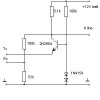
I'm after some validation of this circuit ->
**broken link removed**
I'm after a way of sending/receiving from my car ECU a 12V digital signal
using a uController (AVR).
A kind sole presented the above circuit. Based on the labelling, to transmit
from the car (12V) to uController(5V), place 12V (or 0V) on the collector of
Q1 (labelled K line) and read on Tx.
To transmit from the uController, place 5V (or 0V) on Rx and read
from the K line.
I've also discovered placing 5V (or 0V) on the emitter of Q1
(labelled Tx) works! This freaks me out! Why does this work ?
Anyone got any general suggesions as to whether this is a good
approach. Also, if I want to include optoisolate this circuit (in
both directions) how would I go about doing this given a single line carries
Tx and Rx information?
Thanks in advance!
Adam