Continue to Site

Welcome to our site!

Electro Tech is an online community (with over 170,000 members) who enjoy talking about and building electronic circuits, projects and gadgets. To participate you need to register. Registration is free. Click here to register now.

  • Welcome to our site! Electro Tech is an online community (with over 170,000 members) who enjoy talking about and building electronic circuits, projects and gadgets. To participate you need to register. Registration is free. Click here to register now.

PWM voltage regulator to NON-PWM fan

Status
Not open for further replies.

qwwwizx

New Member
Hi all,

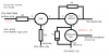
Over the last couple of days I have been trying to use my motherboards FAN PWM output to switch a 12v line down, but I cant really manage to adjust the FAN. I have added a diagram here.

The thing is that when I use a LED it seems to work perfectly lighting up and down when I adjust dutycycle in bios, but when it comes to the fan it seems to stay at full speed, not adjusting up and down.

As far as I know the PWM wire will use a PWM frequency of about 25khz and something between 3.3v to 5v. When its on, it should make the PWM low, meaning that if the wire is not connected the fan should run full speed. Since my only FETS are Logic Level N-Channel fets, I use a PNP transistor to turn that around. When its on, the FET should open, when off it should close. Can anyone here tell me what can be the problem?

**broken link removed**

I have been thinking that I might switch things too fast for a non-pwm FAN in case the FAN have a build in capacitor or something, but I have no idea if that can be the reason.

Anyone?
 

Attachments

  • pwm fan.png
    pwm fan.png
    12.4 KB · Views: 197
Your PNP transistor is connected wrongly. (1) Its emitter should be more positive than its collector. (2) 5V can't turn the transistor off.
You need an inverting level-shifter if you really need to 'turn that around'.
When its on, it should make the PWM low
But do you need the inverting function? Doesn't a low mark/space ratio generally set a low fan speed for pwm fans?
 
Here's a suggested circuit. Version A is for the case where PWM inversion is required. Version B is for the case where it isn't.
Version B would probably need a FET with a lower turn-on voltage than for Version A, because of the Vbe voltage drop of Q4.
FanPWMDriver.gif

Edit: If the fan proves not to like having a high-frequency PWM drive you could try my Synchronous Pulse Delay method instead, with the use of an RC filter to first convert the PWM to a steady voltage:-
https://www.electro-tech-online.com...-and-or-replacement-for-sl100-transistor.551/
 
I can see that now :),

1) I reconnected and now its right, but the system seems still not to work with a Fan.
2) Thats right too, I am used to logic levels, and didnt think about it this time. It will be an issue, but why does it work with a LED when I change the Fan out with a LED and a resistor?

I am pretty sure, but I might be wrong about the need to invert the signal.
 
I will use a little more time on finding the problem with the simple PWM design, because my project is to be able to manage about 10 high-speed Fans, from only one PWM output. Low PWM, below like 16khz, will make the Fan noisy so I need the fast signal and the computers own PWM fan signal should be perfect.

I will try your designs and investigate the third choice with a more steady voltage. I think the steady voltage is what I really need for these to work.
 
I think the steady voltage is what I really need for these to work.
If you filter the PWM to get a steady DC voltage and simply use that with your circuit the FET will get HOT! With my SPD circuit it won't.

I am pretty sure, but I might be wrong about the need to invert the signal.
Can you check your PWM signal with a 'scope?
 
Last edited:
I would love to, but I dont have a scope. I will buy one next month. I get a room for computer and electronics next month, and then I will have space for scope etc. too ;-)

I will take a look at your drawings now.
 
I ordered an oscilloscope now. To much working in blind. Hope it will arrive soon.

Version A did the same as my own circuit. Just kept the FAN spinning at max. Both circuits actually adjust the voltage correct up (readings on my multimeter), when I use a LED and multimeter. Can it be inductance in the FAN that ruin the PWM based voltage?
 
The PWM frequency is probably to high for your fan. Slow it down to a few hundred Hz and see if that isn't better.
 
There is a PWM to analogue voltage converter IC which is easily available in the market. LM358 (I guess), you can look it up on google. All you need to do is give a PWM signal to the IC and it'll give you an analogue output in the given voltage range which can be fed to FET or relay, whatever you're using. Just connect an inverter in the path if you want the inverted function and you're good to go. Besides you can make analogue voltage from PWM by simply using RLC filters. It's an easy task which you can do on your own. If I understand your problem correctly, you don't need to be going through all these issues which you're having right now.

circuit card assembly
 
Last edited:
I will continue project as soon as I recieve the oscilloscope and let you know. I was hoping I could do it without, but with these problems I just feel like working a bit too much in the dark.
 
Status
Not open for further replies.

Latest threads

New Articles From Microcontroller Tips

Back
Top