Continue to Site

Welcome to our site!

Electro Tech is an online community (with over 170,000 members) who enjoy talking about and building electronic circuits, projects and gadgets. To participate you need to register. Registration is free. Click here to register now.

  • Welcome to our site! Electro Tech is an online community (with over 170,000 members) who enjoy talking about and building electronic circuits, projects and gadgets. To participate you need to register. Registration is free. Click here to register now.

PWM to analog output: R/C radio to control analog joystick functions - any ideas?

Status
Not open for further replies.

forrestking

New Member
Hello, I'm new! I'm working on a project and have hit a snag. Presently my only alternative is to create a mechanical mixer to move the cart described below. I appreciate you guys looking at this and will let you knwo how it turns out either way.

I am building a remote controlled electric cart based on an electric wheelchair.

The wheelchair control box contains all of the parts to monitor and charge the batteries while controlling the speed and direction of the wheelcahir motors.

The wheelchair uses a joystick for input. The joystick is a Penny & Giles JC200. ( I have located the spec sheet and downloaded it.) It is connected to the brains of the computer by 5 wires:
red: 12V positive
Green: center tap
Black:" zero voltage supply"
Blue: x-axis output voltage signal
Yellow: Y-axis output voltage signal

Rather than have a servo mechanically move the joystick, I want to remove the joystick and replace it with a non-mechanical interface that connects to a Futaba R/C receiver.

The problem I 'm having is finding a way to change the Pulses that come from the Receiver's output into the correct voltage to replace the joystick.

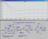
The Futaba Receiver's signal is a square pulse with 0V and 5V levels. The high length of the pulse determines the stick position, 1ms being one extreme, 2ms the other extreme and 1.5ms the center. The time between two rising edges is 20ms.

Do you have any ideas what I could use to convert the Pulses to the corect output voltage?

Here is the link to the existing joystick controller - this is what I am trying to replace: **broken link removed**
 
A micro controller with 4 DAQ's would work. You could probably do it with discrete analog/digital IC's but it'd be pretty complicated.
 
I am looking to keep this simple and hopefully less than a hundred bucks.
One could easily buy a electronic speed controller (ESC) that would match your Futaba transmitter. If one was inclined, then a lone microcontroller could be used to decode the RC receiver pulse stream, and then PWM the forward, reverse, left, and right channels of the joystick during the long synchronization/dead-time cylcle.

Their is tons of stuff on ESC, PPM/PCM decoding, etc. in battlebot, and RC websites/forums.
 
forestking, the easiest way I see of doing it is simply using a micro controller to decode the PPM signals coming from your receiver, then you use software PWM to create an on/off signal through a few transistors into a capacitor/reistor as a low pass filter, that'll give you a basic analog out signal. It would cost well under 100 dollars but it depends on your ability to program and knowledge of electronics in general.
 
Can't you just use a lowpass RC filter? Assuming the pulses are a fixed frequency?
 
That's what I meant by software PWM dk. Should be easy enough to do with an RC low pass. But only if the poster can write code and is comfortable getting a programmer and what not.
 
A microcontroller is not needed. He can convert the PWM signal from the receiver directly into an analog voltage with an RC lowpass filter. First amplify receiver output signals with an op-amp then feed that signal into an RC lowpass filter. Then buffer the analog voltage from the lowpass filter with another op-amp. Choose the amplifier gain so that the output signals from the low-pass filter are the voltage levels that you require.

One thing though...the frequency that the pulses come out of the receiver have to be fixed. For regular RC servos that the receiver normally controls, it is ONLY the on-time of the PWM pulse that matters (the pulses could be of changing frequency and it wouldn't matter since the servos only pay attention to the length of the on-time, not the duty cycle of the square wave). But the LP filter DAC depends on the duty cycle as well, so the pulses must be of a fixed frequency. The receiver is probably fixed frequency, but the frequency might vary between receivers so if you change receivers you might have to readjust things.
 
Last edited:
Dk, you should know how servo signals work, they are NOT straightforward PWM, a low pass filter willl produce a limited voltage range not including either rail and would be useless for his application. You would need to stretch the pulses first. Pulse stretchers are not complicated but like I said, you go the discrete analog/digital route you'll pay for it in the end, a micro controller is the ONLY sollution if the posters doesn't have lots of experiance with electronics. If they have no experience with coding then neither route is going to be easy.
 
The shortest RC pulse is 1ms, the longest is 2ms, repeated every 20ms. That's a full swing duty cycle of 5-10%. At 5 volts through a low pass that would give him an analog range of .25 to .5 volts, not exactly a usable signal. It would have to be DC shifted and amplified, so you're look at 4 opamps minimum. A micro controller is a 1 chip sollution. It's trivial to measure the pulse width and output full scale PWM on four channels into low passes to get rail to rail voltage swings.
 
If the Joystick is fed with 12V, it puts out 6V centered, and swings from 4.8V to 7.2V. Here is a four opamp solution that produces the same amplitude, centered at 6V. It relies on a clean, accurate 12V supply.

It uses 12V rail-to-rail CMOS op-amps. First stage U3 just squares and amplifies the PWM signal so that it swings from 0 to 12V. The RC network produces a voltage whose average value is derived directly from the PWM ratios. It has a lot of ripple, so I pass it through a three-pole Butterworth filter with a cutoff of 1Hz (U2 & U1). The final stage U4 offsets the signal to 6V, and provides gain so that the signal matches the same swing as the Joystick. Varying R1 (65.5K, make it a fixed value in series with a trimpot) will center the swing at 6V.
 

Attachments

  • PWMtoJoystick.jpg
    PWMtoJoystick.jpg
    260.3 KB · Views: 1,022
  • PWMtoJoystickW.jpg
    PWMtoJoystickW.jpg
    370.6 KB · Views: 659
ur screwed

...in other words, just make a mechanical connection from your servos to the joystick...a hell of a lot easier, and cheaoer as well, unless you can program a microcontroller.
 
bigkim, how is four opamps per channel going to be cheaper than a single micro controller? =)
 
ur screwed...in other words, just make a mechanical connection from your servos to the joystick...a hell of a lot easier, and cheaoer as well, unless you can program a microcontroller.

Thanks to everybody for the helpful suggestions. bigkim, you suggestion of a mechanical mixer is how I have the system set up right now - it's chincy, uses too many moving parts, requires its own power supply, is HUGE (like 4"x4"x6"), and the servos and arms are not accurate enough to reliably center the joystick upon startup - an uncentered joystick causes the wheelchair brain to look out, a great safety feature should the radio/wheelchair be powered up while the sticks are deflected on the transmitter...

MikeMl, thanks!!
 
Last edited:
If the Joystick is fed with 12V, it puts out 6V centered, and swings from 4.8V to 7.2V. Here is a four opamp solution that produces the same amplitude, centered at 6V. It relies on a clean, accurate 12V supply.

It uses 12V rail-to-rail CMOS op-amps. First stage U3 just squares and amplifies the PWM signal so that it swings from 0 to 12V. The RC network produces a voltage whose average value is derived directly from the PWM ratios. It has a lot of ripple, so I pass it through a three-pole Butterworth filter with a cutoff of 1Hz (U2 & U1). The final stage U4 offsets the signal to 6V, and provides gain so that the signal matches the same swing as the Joystick. Varying R1 (65.5K, make it a fixed value in series with a trimpot) will center the swing at 6V.

Mike, you are right on with the Voltages - using my cheapie voltage tester I see 11.84 volts being supplied, and the center tap is at 5.91 volts. When at full deflection the measured voltage swing is from 4.82 to 7.09 volts on one axis and 4.84 to 7.20 on the other. Again, cheap equipment being used.

So that brings me to my questions -
1) on your diagram where does the center tap come into play? The existing motor controller goes into lockdown if it does not see 50% of the voltage on the center tap. [Am I understanding joysticks correctly, the center tap voltage never changes, correct?]

2)The R/C receiver uses 6v for power, could I tap into the center tap for this 6V?

3) do I need to worry about the impedance of the circuit? I see it mentioned in the Penny & Giles Technical Specs that are listed, and I wonder, is that just a measurement within the joystick, or might the impedance of the circuit cause me issues?

Thanks again - t
 
Can you use the 11.84V (tied to the top of the joystick) to power my circuit?
If so, disconnect the input to the wheel-char
servo from the TAP on the joystick and connect it to OUT on my circuit.

In the original, the voltage at TAP controls the wheelchair servo. After the change, my circuit generates a voltage at OUT which varies as the RC pulses change. When the RC pulse is 1.5ms, OUT should be half the supply voltage, ie half of 11.84V (similar to what it was out of TAP). You may have to tweak R1 in my circuit to "center" the wheelchair servo when the RC pulse is 1.5ms, and when the RC joystick is trimmed to center...

If you need 6V to power the RC receiver, you can derive that off the wheelchair 12 or 24V using an appropriate regulator. My circuit doesn't care what the amplitude of the 20ms pwm signal is within reason.

I dont think that the series impedance mentioned the joystick spec will matter. If it does, then put a 1.4K resistor in series with "OUT".
 
Last edited:
Don't forget they make quad op amps, you could do each circuit in one device. Maybe someone knows a good device. Just not LM324...
 
Why not change the controller - you have two 12v motors requiring forward and reverse control. A couple of heavy duty R/C Boat units would drive the motors and would connect directly into your R/C Rx. The controllers would also supply suitable power for the Rx.
The cart would be driven like a Tracked vehicle, (Up Down movement of two joysticks on the R/C transmitter), or if it is a computer radio, the joystick outputs can be mixed to give forward/backwards drive and Left/Right steering.

Regards
Ron
 
We have gone from a person asking for a simple solution to finding a way to control the joystick on an existing power control system, to four opamps per channel for analog pulse stretching and voltage amplification, and now we have suggestions on completely ripping out the power electronics and using expensive ESC's to do it with just the RC equipment. You could do this ENTIRE project with 1 micro controller and a single level shift IC or pass transistor through an RC filter.
 
Status
Not open for further replies.

Latest threads

New Articles From Microcontroller Tips

Back
Top