PlaneCrazy
Member
Greetings, all
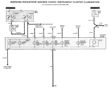
I drive a 1980s Mercedes-Benz, with a series-connected rheostat dimmer for the instrument cluster and console lighting. These rheostats are notoriously fragile, and when they fail, the car is legally and practically unsafe to drive at night. Also, I would like to upgrade the backlighting to LEDs due to their greater brightness and lower heat. So I have been toying with the idea of a drop-in PWM replacement for the finicky, fragile and NLA rheostat.
I have access to two terminals between the battery (via some fuses and switches, of course) and the load. I don't have access to chassis ground. And most OTS dimmers have 4 terminals, not two; furthermore, I would like to use a potentiometer with a through-hole shaft, so I can have a shaft custom-machined to fit the existing knob.
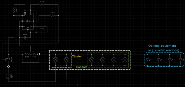
Before I even begin looking at packaging, I have designed this CMOS 555-based circuit that I would like you all to review for me, please.

The yellow circles indicate the terminals where the rheostat unit connects to the rest of the system. The maximum power consumption, based on standard equipment bulbs and max optional equipment, is ±20W. I am aiming for a frequency high enough to prevent flickering for LEDs while being robust enough for incandescent bulbs and quiet enough to prevent artificial tinnitus. I have excluded the fuses and main switch upstream of the battery-side terminal for brevity.
I understand that I need to use a CMOS 555 and a P-MOSFET, since I have no choice but to control the high side of the circuit.
I am open to suggestions, as well as red flags.
Thanks
I drive a 1980s Mercedes-Benz, with a series-connected rheostat dimmer for the instrument cluster and console lighting. These rheostats are notoriously fragile, and when they fail, the car is legally and practically unsafe to drive at night. Also, I would like to upgrade the backlighting to LEDs due to their greater brightness and lower heat. So I have been toying with the idea of a drop-in PWM replacement for the finicky, fragile and NLA rheostat.
I have access to two terminals between the battery (via some fuses and switches, of course) and the load. I don't have access to chassis ground. And most OTS dimmers have 4 terminals, not two; furthermore, I would like to use a potentiometer with a through-hole shaft, so I can have a shaft custom-machined to fit the existing knob.
Before I even begin looking at packaging, I have designed this CMOS 555-based circuit that I would like you all to review for me, please.
The yellow circles indicate the terminals where the rheostat unit connects to the rest of the system. The maximum power consumption, based on standard equipment bulbs and max optional equipment, is ±20W. I am aiming for a frequency high enough to prevent flickering for LEDs while being robust enough for incandescent bulbs and quiet enough to prevent artificial tinnitus. I have excluded the fuses and main switch upstream of the battery-side terminal for brevity.
I understand that I need to use a CMOS 555 and a P-MOSFET, since I have no choice but to control the high side of the circuit.
I am open to suggestions, as well as red flags.
Thanks
Attachments
Last edited: