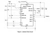
Do you have Vcc=10V ? Should have a capacitor from Vcc to GND.
Do you have "Vref on the left side connected to Vref on the right side?
Is the switch on pin 10 open or closed?
1k pot should be turned so pin 4 and pin 5 have almost the same voltage.
View attachment 111319