Continue to Site

Welcome to our site!

Electro Tech is an online community (with over 170,000 members) who enjoy talking about and building electronic circuits, projects and gadgets. To participate you need to register. Registration is free. Click here to register now.

  • Welcome to our site! Electro Tech is an online community (with over 170,000 members) who enjoy talking about and building electronic circuits, projects and gadgets. To participate you need to register. Registration is free. Click here to register now.

Push Pull problem!!!

Status
Not open for further replies.

pppopey

New Member
Hi everyone

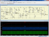
Im facing a problem. I am not able to understand the push pull configuration in this schematic. When I make this circuit on the breadboard, the circuit works till the PWM generator and doesn't work after the BJT, mostly there is a SC in this circuit even if connected properly. If i remove the 3 BJTs and attach the PWM straight to the mosfet,. the circuit works. But i need to have a drive circuit for the Mosfet and I've been told that this push pull drive circuit is good.

Please tell me why it is not working and some solutions to improve this drive circuit or any other options, EXCEPT using a microcontroller.
 

Attachments

  • cct.jpg
    cct.jpg
    355.4 KB · Views: 209
The push-pull circuit as shown works fine in a simulation. If the PNP and NPN transistors are swapped around, however, then there's a short circuit (as you would expect).
I think there must be a wrong connection somewhere on the breadboard. Have you confirmed the connections and pin-outs of the BJTs ?
 
Gee, we went through this circuit in a good bit of detail with you on the other site a week or two ago. I'm attaching an image of the simulation, but I replaced the timing cap with one that's 10nF to get the freq up to ~900Hz; 100nF was just too slow.

What are you using for the transistors? If you don't have 9012 and 9013's, you can use 2N2222 and 2N2907's.

Are you absolutely certain that you have identified the pins on the transistors correctly? This is a very common mistake for people to make. Some datasheets show the pins from the bottom of the package, which can lead to a great deal of confusion.

If you are uncertain, then tell us what is the actual part numbers of the transistors that you are using.
 

Attachments

  • MAX PWM pppopey.png
    MAX PWM pppopey.png
    142.2 KB · Views: 167
Status
Not open for further replies.

Latest threads

New Articles From Microcontroller Tips

Back
Top