Electro Tech is an online community (with over 170,000 members) who enjoy talking about and building electronic circuits, projects and gadgets. To participate you need to register. Registration is free. Click here to register now.
Welcome to our site! Electro Tech is an online community (with over 170,000 members) who enjoy talking about and building electronic circuits, projects and gadgets. To participate you need to register. Registration is free. Click here to register now.
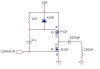
Normally if you take the input high, the NFET switches on and PFET off. If you take it low, the PFET switches on and NFET off.
If the input idles low, the 0.1uF cap charges via the 10k resistor. When it is fully charged, the gate of the PFET is high, so the PFET is off. As the input is low, the NFET is off too.
Take the input high, the 0.1uF cannot discharge quickly as its current is limited by the 10k resistor, so the voltage at the gate of the PFET tries to go 5V above the supply. The 1N4148 catches the excess votlage and discharges the cap into the Vcc rail. As the input is high, the NFET switches on.
When the input goes low, the PFET switches on, passing current to the LC circuit on the output.
take the input high again the NFET switches on and the energy in the LC circuit is allowed to circulate in a loop around NFET, ground, L and C.
Take the input low and the PFET switches on, passing another pulse of energy to the LC circuit and so the circuit continues to operate.
The ac coupling of the input to the PFET means that the PFET is only on for a short amount of time (enough to conduct energy to the LC circuit), but also enabling the PFET to remain switched off (it is held off by the 10 resistor across its gate-source) when the input is idling low.
The circuit is too simple.
Its supply voltage is only 5V so logic-level Mosfets and a 5V p-p input signal must be used.
But when the input is changing then both Mosfets are turned on at the same time which causes a very high shoot-through current in the Mosfets which might destroy them or destroy the power supply.
Usually a push-pull pair of Mosfets are driven from a waveform that has a small amount of dead-time so that one Mosfet turns off before the other Mosfet turns on.
ya i know the output will gives a larger current,but i do not know why and how the current at the output is larger.can you please explain to me.Thank you
The input current to the Mosfets is small and the output current from the Mosfets is high. When a Mosfet completely turns on it has a very low on-resistance. The very low resistance can pass a high current.
That is how Mosfets work.
This site uses cookies to help personalise content, tailor your experience and to keep you logged in if you register.
By continuing to use this site, you are consenting to our use of cookies.