Electro Tech is an online community (with over 170,000 members) who enjoy talking about and building electronic circuits, projects and gadgets. To participate you need to register. Registration is free. Click here to register now.
Welcome to our site! Electro Tech is an online community (with over 170,000 members) who enjoy talking about and building electronic circuits, projects and gadgets. To participate you need to register. Registration is free. Click here to register now.
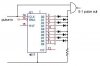
Nice design, Sebi. The output will have an asymmetrical output, due to the two missing pulses. Wildfox, in case your application must maintain duty cycle symmetry, I fleshed out the design I mentioned earlier.
Hi Sebi,
That is almost exactly what I was thinking of. My schematic writing software is so much trouble though.
Your schematic is perfect, what do you use?
i just use the Paint for modification (with copy/paste) of sematics. I have many sematics on HDD, and when somebody need a circuit, i can draw it.(just 5...15min)
Sebi, your circuit will probably put out an unwanted glitch after each group of 4 pulses. Draw a timing diagram which includes propagation delays. I think you can fix it by putting an inverter in the clock line which goes to the counter.
Mogur, I don't know what you're smoking. There's no way that is going to put out a symmetrical duty cycle. First, the 7490 does not have a symmetrical duty cycle. Second, your circuit attempts to create two pulses for every transition of the 7490's output, and if it did, each pulse would have a width equal to the propagation delay of a 74386 gate (about 30 nanoseconds). In fact, for each transition of the 7490's output, you will only get one pulse whose width is equal to twice the propagation delay of a 74386 gate. Again, do a timing diagram.
The only way I know of to get symmetry over a range of frequencies is with a phaselocked loop (PLL), where the VCO (Fout) is running at 4/5 of the input frequency (Fin). You have to divide Fin by 5, divide Fout by 4, and run these two signals to the phase detector of the PLL.
This site uses cookies to help personalise content, tailor your experience and to keep you logged in if you register.
By continuing to use this site, you are consenting to our use of cookies.