Continue to Site

Welcome to our site!

Electro Tech is an online community (with over 170,000 members) who enjoy talking about and building electronic circuits, projects and gadgets. To participate you need to register. Registration is free. Click here to register now.

  • Welcome to our site! Electro Tech is an online community (with over 170,000 members) who enjoy talking about and building electronic circuits, projects and gadgets. To participate you need to register. Registration is free. Click here to register now.

pulse output

Status
Not open for further replies.

arivel

Member
Hi.
can you help me? .
how many ways are there to get what I drew in the attached file?. I prefer not to use micro.
there is no frequency. I had to draw a frequency to make people understand.
dual input voltage and dual pulse output voltage.
bye thank you .
 

Attachments

  • impulso.jpg
    impulso.jpg
    799.1 KB · Views: 231
Wat is the magnitude (voltage) of the input pulse?
What are the pulse width and magnitude requirements of the output pulse?
 
For a low current solution you could 'almost' get there with a handful of discrete components. I say almost, because the output is inverted which is a simple fix... just invert the input. If you want more output current there are ways to do that but would involve a few more transistors on the output stage.

In addition to what Chris said, we need to know the output current. More details.

Pulse Test.JPG
 
I have not specified because I have not yet chosen a fixed voltage. I can however say that I will choose a voltage within the range from + 5-5 to + 7.5-7.5
output pulse voltage as similar as possible to the input one.
I have yet to establish the duration of the impulse, but more or less it will be about ten milliseconds
 
What is the purpose of the circuit? What is the output pulse train connected to? Depending on what you really need, this might be possible with nothing more than 1 capacitor and 1 resistor. Or maybe add two zener diodes to set the output level.
 
I have to apologize because I was in a hurry. this is a volume attenuator.
I need it to drive single coil bistable relays.
in these relays the current flows in both directions.
the signal comes from 2 cd40193 binary meters in cascade.
six bits used so six relays in total.

this link is a different topic but it is related.

... You want the output 0V to be driven or can it float at 0V? Since that level is crossed in the input but not sustained at that level.

that's right. I was going to write it yesterday.
since the relay coil creates overvoltage on shutdown I wonder if a 0 (ground) voltage is better than a floating break.
 
Hi.
can you help me? .
how many ways are there to get what I drew in the attached file?. I prefer not to use micro.

You've been posting multiple threads, all asking for non-micro solutions to pretty complicated questions all connected to the same project.

We're not in the 1960's, USE A MICRO - which would cure all your problems easily, cheaply, take almost no components at all, and allow your project to be greatly enhanced.
 
I am of a certain age and I no longer want to start studying a programming language.
I am also romantically linked to old electronics
 
I am of a certain age and I no longer want to start studying a programming language.
I am also romantically linked to old electronics

When your lover realizes you'll do anything (and accept any behavior) to keep them, the relationship will likely become challenging.

NOTE: This first "session" of relationships counseling with inanimate objects is free - additional sessions are $100/post.
 
I am of a certain age and I no longer want to start studying a programming language.
I am also romantically linked to old electronics

Presumably you don't want to actually 'build' anything?, because you're unlikely to ever get to a working design based on all your posts so far.
 
I am of a certain age and I no longer want to start studying a programming language.
I am also romantically linked to old electronics

If even William Sh. accepted the corona vid vaccine, why not you a simple language for a simple micro? ;)
 
I am of a certain age and I no longer want to start studying a programming language.
I am also romantically linked to old electronics
Ignore the rabble. They lay before us as children, searching for the way. They know not better; but with time, some will learn.

The Analog Kid
 
Last edited:
Even the English are freaked out by this :D

Surely it must have been planned?.
You, a guy from the UK, are asking a guy from Argentina (in Argentina) whether the UK NHS planned a stunt? Funny stuff.
 
I thought of two solutions.
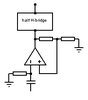
- dual power supply, opamp, half H bridge or Push – pull.
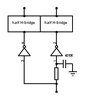
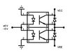
- single power supply, double schmitt trigger inverter, double H half bridge or Push – pull.

in the opamp configuration (fig. driver opamp) I have to use relays with a supply voltage which turns out to be half of the entire dual supply.
I have a little doubt: when the relay switches off does the overvoltage manage to discharge through the double power supply?.

in the double schmitt trigger configuration (fig. driver dual schmitt trigger) I can use relays with the same voltage as the power supply.
this configuration has a peculiarity:
when the relay is off, the two terminals remain live even if it has the same sign. in this case I don't know if it is possible to discharge the overvoltage produced by the coil. there are schmitt trigger buffers capable of delivering up to 40 mA and possibly more. is it possible to use only these without to add the H bridges with mosfet ? or Push - pull with transistor darlinghton ?

in both cases I don't know if it is better to use Push-pull with transistor darlinghton or half H-bridges with mosfet .

I found some integrated circuits on the net:
https://datasheets.maximintegrated.com/en/ds/MAX5054-MAX5057.pdf

- dual power supply . I thought that a pair of phototransistors or photodarlington one on top of the other totem-pole (fig. photodarlington) could be another choice but the on time is shorter than the off time
 

Attachments

  • driver OPAMP.jpg
    driver OPAMP.jpg
    8.7 KB · Views: 176
  • driver dual schmitt trigger.jpg
    driver dual schmitt trigger.jpg
    10.4 KB · Views: 178
  • photodarlington.jpg
    photodarlington.jpg
    10.9 KB · Views: 173
Last edited:
Here's a single coil latch relay driver that should work (i haven't breadboard tested it).
The relay is driven from the same supply but it can be a different supply if needed.
Pulse width is determined by C2 and C4. 10u should provide about 10ms on time at 40mA for the relay shown.
It requires 1 CD4013B chip.

1608584401045.png
 
eTech , What happens when power is cycled on/off? What is the OP expecting will happen?
 
Status
Not open for further replies.

Latest threads

New Articles From Microcontroller Tips

Back
Top