Never mind calculating the frequency since it is determined by the output high time plus the output low time that you need to calculate.
The datasheet for a 555 says that the charge time of the timing capacitor is 0.693 times (Ra + Rb) x C, and the discharge time is 0.693 x Rb x C.
Then the discharge time is the shortest so it should be the burst time of 196us or more. You need an RC time of 196 divided by 0.693= 283us. Use a 10nF capacitor and a 30k resistor for Rb for an RC of 300us then the burst timing will be 300us x 0.693= 208us.
Add a 6.2k resistor for Ra then the charge time will be (30k + 6.2k) x 10nf x 0.693= 251us. The total cycle time is 208us + 251uS= 458us and the frequency is 1 divided by 458us= 2183Hz.
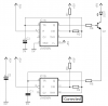
But how will you use it to turn the 56k oscillator on and off?
The datasheet for a 555 says that the charge time of the timing capacitor is 0.693 times (Ra + Rb) x C, and the discharge time is 0.693 x Rb x C.
Then the discharge time is the shortest so it should be the burst time of 196us or more. You need an RC time of 196 divided by 0.693= 283us. Use a 10nF capacitor and a 30k resistor for Rb for an RC of 300us then the burst timing will be 300us x 0.693= 208us.
Add a 6.2k resistor for Ra then the charge time will be (30k + 6.2k) x 10nf x 0.693= 251us. The total cycle time is 208us + 251uS= 458us and the frequency is 1 divided by 458us= 2183Hz.
But how will you use it to turn the 56k oscillator on and off?
") but now, the led indicating the output is ON irrespective of obstacle. It goes off only when i remove the IR led for the board.
but now, the led indicating the output is ON irrespective of obstacle. It goes off only when i remove the IR led for the board.