Continue to Site

Welcome to our site!

Electro Tech is an online community (with over 170,000 members) who enjoy talking about and building electronic circuits, projects and gadgets. To participate you need to register. Registration is free. Click here to register now.

  • Welcome to our site! Electro Tech is an online community (with over 170,000 members) who enjoy talking about and building electronic circuits, projects and gadgets. To participate you need to register. Registration is free. Click here to register now.

proximity sensor

Status
Not open for further replies.

varuntejavarma

New Member
Hello,

I want to build a Low cost proximity sensor for an automatic sense and spray device and i have choosen IR reflective property for this application. I have modulated the signal at 38khz frq and used a tsop38 sensor at detector side. But, I could acheive only a range of 10 cms. I have also tried using high intensity IR led's. I have tried different means but I could not acheive a long range with IR sensor.

1. In general, I want to know, what is the maximum range of detection possible using a low cost IR sensor with 5v supply??

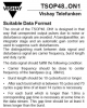
In the mean time i have bought this product and opened the circuit.
**broken link removed**

It consists of only one diode. but i dont know which type of sensor it is. It cannot be PIR sensor. I think it triggers output with the change of light falling on it. It works very well upto 1.5 metre. The yellow led is just to indicate the status of the freshner. it blinks to show that the freshner is ready to detect any movement. if its stable it means the freshner is in sleep mode after completing a spray.
The actual detection is done by the large diode. It works on passive detection. so there is no transmitter in the circuit. And it is not even pir sensor.
my observation:
when an obstacle is in front of the sensor, it doesnt trigger the output. it triggers only when the obstacle moves away. by this i think it works on movement of shadows. maybe it takes in the surrounding light as default and when there is a obstacle movement there would be change of light and the output is triggered. This is what i am thinking. I am not sure. Is there any possibility for a diode to work in that way. If yes, which type of diode is used and how does it work.

How to find out which type of sensor is used in this circuit.
how does this sensor work and what is its principle.

It would be very helpfull if anyone could assist me in this project. It is my first project in electronics and i am tring the method of learning by doing and got no help around me
 
i think it works on movement of shadows. maybe it takes in the surrounding light as default and when there is a obstacle movement there would be change of light and the output is triggered.
That would be my guess. The diode might be driven from a constant voltage or constant current source and its current/voltage monitored by an ADC or Schmitt trigger input of the control chip. Many diodes in a transparent/translucent body exhibit photo-sensitivity, but some are more sensitive than others.
 
I think your issue is the light o/p of the led, try and get a dead remote and salvage the infra red led from it, they tend to be high o/p.
Also I found with the tssop devices you need to filter the supply, try a 100r resistor in series with the + supply and a 100u cap across the tssop power supply pins.

You should be able to get 10 to 15 meters, in fact you might need to put the tssop in a tube as light may well pass round a person and keep the o/p active.

Edit: One last thing a tssop device's o/p will not stay low (active) long as they are capacitively coupled internally, you need to transmit bursts of 38kc's infra red about 1/4 second long with a 1/4 sec gap to keep the o/p low, so you need 2 555's for that, I think I have a link somewhere from someone who's done it.
 
Sense motion then spray a scent?
I got a device like that for free as a sample. The Air Wick company hopes I will buy their very expensive bottles of perfume for it. Never!
It came with three AA alkaline batteries that lasted about 1 month and it is triggered by its PIR or by its timer. The PIR does not detect my small dog but my dog got sprayed by another one.
 
The PIR does not detect my small dog but my dog got sprayed by another one.
Sprayed by another sensor-spray, or by another dog? :)
 
One last thing a tssop device's o/p will not stay low (active) long as they are capacitively coupled internally, you need to transmit bursts of 38kc's infra red about 1/4 second long with a 1/4 sec gap to keep the o/p low, so you need 2 555's for that, I think I have a link somewhere from someone who's done it.

ok. I have used only one 555 timer. I have uploaded the circuit diagram i have used. I have used 56khz carrier freq and tsop4856 at the receiver side. According to the circuit, are the signals pulsed at 50 % on off or does the led emit continous signals. If it emits continous signals, what changes should i make in the circuit for on off signals and how could i vary the on off period.
 

Attachments

  • DSC_0966[1].jpg
    DSC_0966[1].jpg
    1.9 MB · Views: 182
The datasheet for the TSOP IR receiver (and almost all of their IR receivers) shows that it needs its 56kHz pulses turned on and off in bursts of 10 cycles or more for the AGC to keep the gain high. If it receives continuous 56kHz pulses the AGC reduces the gain a lot so the IC will not respond to 56kHz compact fluorescent light bulbs and it might not detect your IR pulses.
 
yes, I have read the info in datasheet. I have found this basic circuit in internet and believed that the led is turned on off with 50%duty cycle. after seeing my circuit, can someone explain if the signals are turned on off or just sending a 56 khz continous signal. If not how could i turn them on and off. an explanation with circiut diagram would be very helpful for me
 
You need a second 555 (or use a 556 which is a dual 555) to turn on and off the 56kHz oscillator to make bursts of 56kHz.
 
56khz for 250msec, then 250msec of silence, then start over.

Have a look a this:

**broken link removed**
 
56khz for 250msec, then 250msec of silence, then start over.
Your attachment shows a circuit that blasts bright IR for a very short distance.

I think the instructions in the datasheet should be followed, "For long burst lengths, the gap time should be 4 times longer than the burst."
 

Attachments

  • TSOP4856.png
    TSOP4856.png
    82.6 KB · Views: 167
ok now i understand. but i still have a silly doubt. while calculating carrier frequency i came across formula for duty cycle. so, doesnt it mean the on off period?? if not, what does that mean??

For selecting the frequency of period is there anything i should keep in mind or could i select any frequency. which would be better for 56 khz
 
The timing capacitor in a 555 oscillator charges for a longer time through two resistors in series but discharges for a shorter time through one resistor. When charging, the output goes high. Then the circuit linked here with the 556 IC does the duty-cycle backwards. The 56kHz pulses for the IR LED are turned on for longer time than the gap between bursts.

The datasheet for a 555 has a formula and a graph for calculating the resistors and capacitor values for a certain frequency.
 
Yes, I have gone through it for frequency calculation. But, should I consider anything for selecting the frequency value at which i am going to on off my signal. which value would be better for 56 khz
 
you want 50% duty cycle, its the ratio of the on time to the off time, 100% would be on all the time.
You could reduce the duty cycle if you really want to reduce power consumption (and range).
 
The burst length should be 10 cycles of the 56kHz or longer (select 11 cycles) and the gap time between bursts should be at least 14 cycles for a burst length up to 70 cycles, select 15 cycles of 56kHz. Then the minimum burst time is 196us and the minimum gap time is 267us for a maximum frequency of 2.16kHz.

How will you turn the 56kHz 555 oscillator on and off? The circuit linked has the duty-cycle backwards.
 
ok. so, as per the data sheet, I have to select the gap time 4 times that of burst length. for ex: If I select 11 cycles of 56 khz as burst length, then i should select min of 44 cycles as gap time which would give me 196us burst length and 783us gap time for freq 1,02 khz. Please let me know if i am right and
 
You did not read the datasheet and my post of a part of it.
"For each burst that is longer than 1.8ms a ----- gap time ----- should be at least 4 times longer than the burst". 1.8ms is a very long burst time resulting in a low frequency.

The datasheet also says, "After each burst which is between 10 cycles and 70 cycles a gap time of at least 14 cycles is necessary".
11 cycles of 56kHz is a burst time of only 196us, not 1.8ms which is 9.2 times longer.
Then the gap time can be 14 cycles of 56kHz= 249us. The total time is 196us + 249us= 445us and the frequency is 2.25kHz.
But with a burst of 11 cycles the gap time can be longer then the frequency can be lower.
 
ok. now i understand. And for the carrier freq, I have calculated R1, R2, C values online and got 56 khz in oscilloscope by adjusting pot at R1.
How could i calculate res and cap values for 2.25 khz. Because i could do the same and adjust the pot at r1 and get 2.25 khz. but this time i have to get both freq and the duty cycle.
Please dont mind for my basic doubts. I am kind of slow :( . It would be very helpful if you could tell me how to do it so that i can do it before weekend
 
Heres a site to calculate the freq as well as high and low times for a 555, if you design it ballpark then use a pot to trim the freq, by doing this you might mess up the duty cycle a little but dont worry about it being exact.

**broken link removed**

Heres another site that shows you calulations for freq and adjustable duty if you want to go that route.

**broken link removed**

Another interesting site with 555's, somewhere in here theres a adjustable freq and duty cycle 555 circuit.

**broken link removed**
 
Status
Not open for further replies.

Latest threads

New Articles From Microcontroller Tips

Back
Top