**broken link removed**
+
**broken link removed**
=
**broken link removed**
(Park-Aid - RED - Page40)
(Park-Aid Modification - RED - Page138)
R1_____________10K 1/4W Resistor
R2,R5,R6,R9_____1K 1/4W Resistors
R3_____________33R 1/4W Resistor
R4,R11__________1M 1/4W Resistors
R7______________4K7 1/4W Resistor
R8______________1K5 1/4W Resistor
R10_____________1K 1/4W Resistors
R15_____________3K3 1/4W Resistor
R16___________330K 1/4W Resistor
R17___________470K 1/4W Resistor
R18___________150K 1/4W Resistor
C1,C4___________1µF 63V Electrolytic or Polyester Capacitors
C2_____________47pF 63V Ceramic Capacitor
C3,C5_________100µF 25V Electrolytic Capacitors
C6______________1µF 63V Electrolytic or Polyester Capacitor
D1_____________Infra-red LED
D2_____________Infra-red Photo Diode (see Notes)
D3,D4__________1N4148 75V 150mA Diodes
D5-7___________LEDs (Any color and size)
D8,D9,D10______1N4148 75V 150mA Diodes
IC1,IC4_________555 Timer IC
IC2___________LM324 Low Power Quad Op-amp
IC3____________7812 12V 1A Positive voltage regulator IC
BZ1___________Piezo sounder (incorporating 3KHz oscillator)
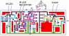
IC1 forms an oscillator driving the infra-red LED by means of 0.8mSec. pulses at 120Hz frequency and about 300mA peak current. D1 & D2 are placed facing the car on the same line, a couple of centimeters apart, on a short breadboard strip fastened to the wall. D2 picks-up the infra-red beam generated by D1 and reflected by the surface placed in front of it. The signal is amplified by IC2A and peak detected by D4 & C4. Diode D3, with R5 & R6, compensates for the forward diode drop of D4. A DC voltage proportional to the distance of the reflecting object and D1 & D2 feeds the inverting inputs of three voltage comparators. These comparators switch on and off the LEDs, referring to voltages at their non-inverting inputs set by the voltage divider resistor chain R7-R10.
The original Park-aid circuit was retained, but please note that the input pins of IC2B, IC2C and IC2D are reversed. LEDs D5, D6 and D7, as also resistors R12, R13 and R14 are omitted. IC2B, IC2C and IC2D outputs drive resistors R15, R16 and R17 through D8, D9 and D10 respectively, in order to change the time constant of a low frequency oscillator based on the 555 timer IC4.
This allows the Piezo sounder to start beeping at about 2 times per second when bumper-wall distance is about 20 cm., then to increase the beeps to about 3 per second when bumper-wall distance is about 10 cm. and finally to increase further the beeps frequency to more than 4 beeps per second when the distance is about 6 cm. or less.
I've come up with this pcb layout, but I'm not sure if it's 100% accurate. Can you please give me a hand and verify it?
**broken link removed**
**broken link removed**
**broken link removed**
There's another resistor soldered directly on pins 2 and 13 of the LM324, but it doesn't show on the layout.
+
**broken link removed**
=
**broken link removed**
(Park-Aid - RED - Page40)
(Park-Aid Modification - RED - Page138)
R1_____________10K 1/4W Resistor
R2,R5,R6,R9_____1K 1/4W Resistors
R3_____________33R 1/4W Resistor
R4,R11__________1M 1/4W Resistors
R7______________4K7 1/4W Resistor
R8______________1K5 1/4W Resistor
R10_____________1K 1/4W Resistors
R15_____________3K3 1/4W Resistor
R16___________330K 1/4W Resistor
R17___________470K 1/4W Resistor
R18___________150K 1/4W Resistor
C1,C4___________1µF 63V Electrolytic or Polyester Capacitors
C2_____________47pF 63V Ceramic Capacitor
C3,C5_________100µF 25V Electrolytic Capacitors
C6______________1µF 63V Electrolytic or Polyester Capacitor
D1_____________Infra-red LED
D2_____________Infra-red Photo Diode (see Notes)
D3,D4__________1N4148 75V 150mA Diodes
D5-7___________LEDs (Any color and size)
D8,D9,D10______1N4148 75V 150mA Diodes
IC1,IC4_________555 Timer IC
IC2___________LM324 Low Power Quad Op-amp
IC3____________7812 12V 1A Positive voltage regulator IC
BZ1___________Piezo sounder (incorporating 3KHz oscillator)
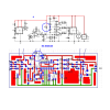
IC1 forms an oscillator driving the infra-red LED by means of 0.8mSec. pulses at 120Hz frequency and about 300mA peak current. D1 & D2 are placed facing the car on the same line, a couple of centimeters apart, on a short breadboard strip fastened to the wall. D2 picks-up the infra-red beam generated by D1 and reflected by the surface placed in front of it. The signal is amplified by IC2A and peak detected by D4 & C4. Diode D3, with R5 & R6, compensates for the forward diode drop of D4. A DC voltage proportional to the distance of the reflecting object and D1 & D2 feeds the inverting inputs of three voltage comparators. These comparators switch on and off the LEDs, referring to voltages at their non-inverting inputs set by the voltage divider resistor chain R7-R10.
The original Park-aid circuit was retained, but please note that the input pins of IC2B, IC2C and IC2D are reversed. LEDs D5, D6 and D7, as also resistors R12, R13 and R14 are omitted. IC2B, IC2C and IC2D outputs drive resistors R15, R16 and R17 through D8, D9 and D10 respectively, in order to change the time constant of a low frequency oscillator based on the 555 timer IC4.
This allows the Piezo sounder to start beeping at about 2 times per second when bumper-wall distance is about 20 cm., then to increase the beeps to about 3 per second when bumper-wall distance is about 10 cm. and finally to increase further the beeps frequency to more than 4 beeps per second when the distance is about 6 cm. or less.
I've come up with this pcb layout, but I'm not sure if it's 100% accurate. Can you please give me a hand and verify it?
**broken link removed**
**broken link removed**
**broken link removed**
There's another resistor soldered directly on pins 2 and 13 of the LM324, but it doesn't show on the layout.
Last edited:
")