Continue to Site

Welcome to our site!

Electro Tech is an online community (with over 170,000 members) who enjoy talking about and building electronic circuits, projects and gadgets. To participate you need to register. Registration is free. Click here to register now.

  • Welcome to our site! Electro Tech is an online community (with over 170,000 members) who enjoy talking about and building electronic circuits, projects and gadgets. To participate you need to register. Registration is free. Click here to register now.

Proteus 7 Simulation

Status
Not open for further replies.

Wilksey

Member
Hi Guru's

I wonder if someone can help me out.

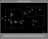
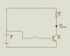
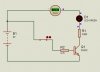
I am using Proteus 7 for circuit simulation, I am attemping a simple LED / SWITCH from a battery via a transistor, now, when the battery is set to 12v the transistor switches fine, when I drop the voltage to 5v it doesn't switch.

It works without the transistor so I know theres something wrong with the transistor sim, it's a standard NPN from the simulation library.

Any ideas how to make it work with something other than 12v?

Thanks

Wilksey.
 
Ok, I think I have attached it properly.

B1 and RL1 was set to 12v, and it worked fine, the relay has voltage etc, I can replace this with a LED to achieve the same desired results.

As is now, with B1 set to 5v the transistor doesn't switch.

This was taken directly from a Proteus sample btw.

Thanks
 

Attachments

  • trans.jpg
    trans.jpg
    66.1 KB · Views: 2,508
Move the pot slider. The problem probably is though that you just changed the label of the of the relay and/or power supply instead of changing the component value.
Right click the relay, not the label.
 
That is not the problem, but thanks for the info.

I have another simple example.

Please note, R1 in the picture has been changed to 1k for 12v and 330R for 5v on the actual simulation.

Battery B1 at 12v, switch works and transistor switches on LED.

Battery B1 at 5v, switch "works" i.e. changes state, but transistor does not switch LED, take transistor out of line, and connect LED to switch direct, works fine.

I'm sure there must be a setting in Proteus for the transistor but I just cant find where it is.

Any help?
 

Attachments

  • trans.jpg
    trans.jpg
    25.5 KB · Views: 5,068
That is not the problem, but thanks for the info.

I have another simple example.

Please note, R1 in the picture has been changed to 1k for 12v and 330R for 5v on the actual simulation.

Battery B1 at 12v, switch works and transistor switches on LED.

Battery B1 at 5v, switch "works" i.e. changes state, but transistor does not switch LED, take transistor out of line, and connect LED to switch direct, works fine.

I'm sure there must be a setting in Proteus for the transistor but I just cant find where it is.

Any help?

You can't expect an LED to light up brightly with a forward current of approximately 230µA.

If you replace the current limiting resistor value by 180Ω the LED gets almost 20mA.

Here are two examples, one using a 9V battery and the other a 3.6V battery. The only thing to change for the same forward current is the value of the current limiting resistor.

Notice that the forward current stays the same using the appropriate resistor.

Boncuk

P.S. You can't change the transistor data, but you can change the LED data. Proteus ISIS uses standard values of Uf=2V and If=10mA. You might change those values by right clicking on the LED and change the values in the pop up window.

With a voltage source of 5V and the standard LED values the LED forward current is 2.3mA using a 1K resistor. The current increases to 3mA if you connect the LED directly to the voltage source - still glowing very faintly.
 

Attachments

  • 3,6V-BAT.gif
    3,6V-BAT.gif
    8.3 KB · Views: 2,100
  • 9V-BAT.gif
    9V-BAT.gif
    8.3 KB · Views: 4,293
Last edited:
Hi Boncuk,

Thank you for your reply.

I tried simulating your circuits, but got nothing on the DC Ammeter in Amps, MilliAmps or MicroAmps.

I have attached a pic, I had to put the LED in Digital mode for it to even light up, I've tried various settings, but nothing seems to work.

What am I doing wrong?

Thank you.

Wilksey
 

Attachments

  • ckt.JPG
    ckt.JPG
    16.8 KB · Views: 1,502
Hi Wilksey,

as far as I can see nothing is wrong with your circuit. May be you missed doing a "real" connection somewhere.

To make a schematic use a grid and leave at least a short distance (one grid line, better use two to get voltage probes into the circuit.) between two parts to connect. Very often the switches won't connect correctly. If you draw the net from the switch to another part it works in every case, vice versa the switch might not connect, because it's not located perfectly on the 1/10inch grid. Use F2 or click "snap 1/50th" (View).

To get a better readout of the am-meter switch it to mA. (use the right mouse button to change settings) Use voltage probes (left hand tool bar the icon with a probe and V) along your nets and look for changes while the simulation is running.

E.g. if the base voltage remains unchanged when closing the switch you've found the problem. In that case delete the net and redraw from the switch to the base resistor.

Boncuk
 
Last edited:
I do use the grid, but the image export removes the background etc.

I changed the LED back to analog and it started working, I have relays dropped from the transistor now and it's working perfectly, I am simulating from a PIC18 output to drive the Transistor, and that works perfectly also.

Many thanks for all your help, I completely forgot about the Vf when simulating the resistor value, I dropped it to 250R and it works fine. 180 gives me 27mA.

Thanks again.

Wilksey.
 
Status
Not open for further replies.

Latest threads

New Articles From Microcontroller Tips

Back
Top