Continue to Site

Welcome to our site!

Electro Tech is an online community (with over 170,000 members) who enjoy talking about and building electronic circuits, projects and gadgets. To participate you need to register. Registration is free. Click here to register now.

  • Welcome to our site! Electro Tech is an online community (with over 170,000 members) who enjoy talking about and building electronic circuits, projects and gadgets. To participate you need to register. Registration is free. Click here to register now.

Project help design an op-amp

Status
Not open for further replies.
One thing I would say is that sim schematics are more difficult to follow than well drawn conventional schematics: the OP implied this.

Could I impose on you and, if you have some available time, do a run on circuit #13.

Well drawn schematics can be assembled in simulation software as well as Cad programs. I doubt anyone uses a drafting board anymore.

Sloppiness is a function of the person drawing, not the tool being used.

I will do the circuit in post #13 anyway when I get home.

If we held newbies to drawing standards, they would be a one and done user of this forum. At best, we can answer with clear drawings and hope they learn from that example.
 
Last edited:
Well drawn schematics can be assembled in simulation software as well as Cad programs.

Right.

I doubt anyone uses a drafting board anymore.
I know quite a few for home work, as I did when my home Protel license expired. But I know what you mean for pros but many new posters on ETO use paper sketches.

Sloppiness is a function of the person drawing, not the tool being used.
That is true generally, but some packages do limit what you can do.

I will do the circuit in post #13 anyway when I get home.

That is very kind. But Mike has already run a good sim on circuit of post #13.

If we held newbies to drawing standards, they would be a one and done user of this forum.

Agree- I wasn't suggesting that for a moment.

At best, we can answer with clear drawings and hope the learn from that example.

We are singing from the same hymn sheet here.

spec
 
Last edited:
... One thing I would say is that sim schematics are more difficult to follow than well drawn conventional schematics: the OP implied this. ...

No, the TS said that he could not open a .asc file which is what I posted after he posted an LTSpice schematic. Because he posted output from LTSpice, I assumed he could open a ready-to-sim .asc file. Apparently, he was away from the computer that could open that type of file, so I posted a screen shot of the LTSpice circuit and plots as a thumbnail.

I am curious; did you click on the thumbnail? Could you read it? I am in the habit of (almost) always posting thumbnails, not the huge in-line pictures you do, which some forum members consider bad forum etiquette. If people cannot read the image after they click on a thumbnail, I need to know that?

Hy Mike,

I just clicked on the thumbnail and could not get your mean little :D images big enough to read. It seems a shame that you should do all that work and then hide the results away almost as though you are ashamed of them.

I do know about the etiquette thing but feel that it is much clearer and easier to follow to have the schematic or other images up front. My schematics are not huge. Most times I take particular care to get the size right for easy viewing, in my opinion that is. I know a few people who watch ETO and they are not keen on thumbnails. After all, if you are reading a book, even an ebook you dont have to keep clicking on thimbnails. If you had to it would be a real pain. As for .asc files they just dont bother. For a start, they don't have LTSPICE. This is a subject that I may post on the 'Site Issues' forum some time. I am not saying that there is not a place for thumbnails though- they are good for ancillary information.

You will notice that I also give links to supporting data rather than post an image, data sheets especially. This aids understanding of schematics- in my opinion anyway.

spec

PS. The posts that JJ did in post #56 are a model of clarity and I would suggest they should be used as an example, once again in my opinion. ronsimpson has also just done an excellent LTSPICE presentation: https://www.electro-tech-online.com/threads/resonance-in-a-400v-ac-circuit.148131/#post-1264445
 
Last edited:
...I just clicked on the thumbnail and could not get your mean little :D images big enough to read. ...
I wonder if this is a browser thing? I am using Firefox, and the thumbnails render just fine when I click on thumbnail and it opens into a new tab in the browser.

Here is the image of post #55 again. I put it in-line two ways, first as a .gif followed by a .jpg. I also put in two thumbnails, one of the .gif, and the other of the .jpg. Please look at all four, and tell me what you see...

gif full image:

s5.gif


thumbnail of gif:

s5.gif

jpg full image:

s5.jpg


thumbnail of jpg:

s5.jpg
 
Joe,

it would be helpful to see the deviation from the ideal function that Tina predicts with the OPA192, sort of like I did... Unfortunately, the plot does not answer that question very well. Could you tabulate Vo as well as Vsensor?

btw, your .png opened perfectly in its own new tab when I clicked on it in Firefox.
 
Mike,

Yes it does, although when I open it in chrome, it's still a little smaller, as seen by the words being slightly blurred. When at 100% it's clear as a bell. Of course, my poor eyesight could be messin' with me.

Give me a few and I'll tabulate the Output.
 
MikeMl

I'm not sure on how to do what you requested in TINA, however, In post processing, I did do it in excel. I have two graphs, one is comparing the simulated output to the desired and the other is the simulated output to the calculated.

There is a pSpice model for the OPA192 at TI.

Anyway, here is the error graph,

On edit: I uploaded the exported output of the simulation as a text file (tab delimited).
 

Attachments

  • Spec-13-error.png
    Spec-13-error.png
    19.1 KB · Views: 258
  • Spec-13-data.txt
    23.1 KB · Views: 287
Last edited:
JJ, glad to see that I'm not the only member using TI's TINA sim...

I have the full TINA educational version, not a student version, and have used it since I left electronics workbench about the time multisim was "born". I don't know the limitations of TINA-TI. I know LT Spice takes some shortcuts, where I can have irregular circuit errors ... typically by not having series resistances on voltage sources and shunt resistance on current sources, by providing those automatically. I've read a few articles on the differences ... well after I chose not to use LTSpice. I do enjoy the fact that there are many others out there and MikeMI and others certainly work LTSpice with ease. Just like in the case above, I have to do post processing where they did it directly, but that could be my own fault of not delving more into TINA, and I'm assuming I'm the weakest link in that area.
 
I wonder if this is a browser thing? I am using Firefox, and the thumbnails render just fine when I click on thumbnail and it opens into a new tab in the browser.

Here is the image of post #55 again. I put it in-line two ways, first as a .gif followed by a .jpg. I also put in two thumbnails, one of the .gif, and the other of the .jpg. Please look at all four, and tell me what you see...

gif full image:

View attachment 99585

thumbnail of gif:

View attachment 99585

jpg full image:

View attachment 99586

thumbnail of jpg:

View attachment 99586

I am using the latest Firefox.

Laptop screen: 15.6" diagonal

Resolution: 1920 by 1080 native

Both your .gif and .jpg render 220mm wide and are clear, including the text.

The gif thumbnail clicks to 140mm wide in a new tab and the text is not clear

The jpg thumbnail clicks to 190 mm wide in a new tab and the text is clearer.

I usually expand/contract an image by using Ctrl plus + or - but if I do that with either expanded thumbnails the tab closes.

I have just noticed though, that at the top right of the expanded images, in addition to a cross to close the tab, there is also an arrow which, if clicked does expand the image and improve legibility of the text.

It would be nice if your thumbnails simply expanded to display as the gif and jpg immediately.

I find your upfront images much easier to use, rather than clicking on thumbnails and also for Joe's work

I do agree on reflection that my schematics could be smaller.

spec
 
Last edited:
Here ya' go ... Spec (post 13)
Nice Joe,

One thing though the size of the text top left was too small in relation to the other text. I could Ctrl and + to expand it though without the window closing.

spec
 
If you mouse over the picture in the new tab, and see a + within a circle, it's because the graphic is not at it's full size. A quick click will bring it to 100% of it's size. The lettering is fine at 100%.
 
If you mouse over the picture in the new tab, and see a + within a circle, it's because the graphic is not at it's full size. A quick click will bring it to 100% of it's size. The lettering is fine at 100%.
Text still too small Joe.
Suggest it would be better to keep all text pretty much same size- that reminds me of a story that I will tell some time:)

spec
 
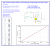
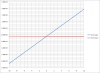
Given that the pressure sensor produces an output voltage (Vs : sensor output voltage) according to the equation Vs = (P x 0.131 )+ 1.683. This equation can be expressed in terms of pressure (P) versus sensor voltage (Vs). ie.
P = (Vs - 1.683)/0.131

You are to design the amplifier circuit for this sensor using any combination of inverting amplifiers, non-inverting amplifiers, summing amplifiers together with a 1V reference voltage source. The two input signals of this circuit are sensor voltage (Vs ) and an 1V reference source (Vref ) and the circuit should produce an output voltage (Vo) indicating the pressure (psi) according to the equation Vo = P (psi)

i.e When P = 0 psi , Vo = 0V and
P = 10 psi, Vo = 10V.
P = -10 psi, Vo = -10V.

STANDARD VALUES FOR RESISTORS AND CAPACITORS
(a) The standard E-12 values for fixed resistors are in the following ratios: 1 : 1.2 : 1.5 : 1.8 : 2.0 : 2.2 : 2.7 : 3.3 : 3.9 : 4.7 : 5.6 : 6.8 : 8.2.
Examples: 100, 120, 150, 180, 220, 270, 330, 390, 470, 560, 680, 820Ω OR 1k, 1.2k, 1.5k, 1.8k, 2k, 2.2k, 2.7k, 3.3k, 3.9k, 4.7k, 5.6k, 6.8k, 8.2kΩ OR 10k, 12k, 15k, 18k, 22k, 27k, 33k, 39k, 47k, 56k, 68k, 82kΩ OR 100k, 120k, 150k, 180k, 220k, 270k, 330k, 390k, 470k, 560k, 680k, 820kΩ OR 1M, 1.2M, 1.5M, 1.8MΩ, etc.
(b) The ratios for the standard values of the various types of capacitors are as follows:
(i) pF range – 1: 1.2 : 1.5 : 1.8 : 2.2 : 2.7 : 3.3 : 3.9 : 4.7 : 5.6 : 6.8 : 8.2 Examples: 100pF, 120pF, 150pF, 180pF, 220pF, 270pF, 330pF, 390pF, 470pF, 560pF, 680pF, 820pF, etc. (
ii) nF range – 1: 1.2 : 1.5 : 1.8 : 2.2 : 2.7 : 3.3 : 3.9 : 4.7 : 5.6 : 6.8 : 8.2 Examples: 10nF, 15nF, 33nF, 47nF, 68nF, 82nF, 100nF, 150nF, 220nF, 330nF, 470nF, 680nF, etc.
(iii)µF range – 1: 1.2 : 1.5 : 1.8 : 2.2 : 2.7 : 3.3 : 3.9 : 4.7 : 5.6 : 6.8 : 8.2 Examples: 1µ, 2.2µ, 3.3µ, 4.7µ etc..

1. REWRITE THE EQUATION WITHE INPUT ON ONE SIDE AND OUTPUT ON OTHER SIDE
2. CHOSE THE AMPLIFIERS AND DESIGN
3. SCHEMATIC OR CIRCUIT DIAGRAMS
4. ERROR CALCULATION OF THE COMPONENT (MUST BE LESS THAN 5%)
5. COMPONENT LIST
 
Did you read all the pages before repeating the same question you asked in post number 1?

Calculate the output voltage when you have zero psi. What is the input voltage at zero psi?

Start there.
 
Status
Not open for further replies.

New Articles From Microcontroller Tips

Back
Top