Continue to Site

Welcome to our site!

Electro Tech is an online community (with over 170,000 members) who enjoy talking about and building electronic circuits, projects and gadgets. To participate you need to register. Registration is free. Click here to register now.

  • Welcome to our site! Electro Tech is an online community (with over 170,000 members) who enjoy talking about and building electronic circuits, projects and gadgets. To participate you need to register. Registration is free. Click here to register now.

Programming a PLC

Status
Not open for further replies.
hmmm, pictures above apear in reverse order. anyway...
although you CAN enter any program without it, this little baby saves a LOT of frustration (i know because i tried)
 

Attachments

  • vl_programming_cable.jpg
    vl_programming_cable.jpg
    65.4 KB · Views: 841
thanks a lot panic mode and instruite!
About the data cable i have it, so no problem there.
I could do the main function of the alarm, u can see in the pic that the imputs are, the panic button, the reed switches (represented with a switch as it's the same, when all the reed switches are closed it's like a normaly closed switch, and if any of them opens it triggers alarm), and the 3 optic sensors.

The thing i have to do with the second button (reed switch), but couldnt find out how, is that i need to add a function that trigger if button in unpressed (circuit is open), and not when the button is pressed.

So, if the panic button is pressed, the optic sensors are triggered or the reed switches are open it triggers the boozer and the lamp for an amout of seconds.

i need to make a function that arms and disarms the alarm using the buttons of the PLC, so if sensors, are triggered the boozer wont sound.

Thanks mates, for real
 

Attachments

  • screen1.jpg
    screen1.jpg
    31.1 KB · Views: 809
Hi
Panic mode - Gr8 job!!!
PinksteR,
Sorry I have Japanese OS on my comp so couldnot install the software
So I wont be able to post any screenshots like panic mode :(
As for your reed switches queery
The thing i have to do with the second button (reed switch), but couldnt find out how, is that i need to add a function that trigger if button in unpressed (circuit is open), and not when the button is pressed.
since you want the logic to be triggered when the switch is open then
you can use a "Not logic" between the secon input (reed switch) and the OR gate.
For your second querry
i need to make a function that arms and disarms the alarm using the buttons of the PLC, so if sensors, are triggered the boozer wont sound.
What do you exatcly mean by buttons of PLC??
Do you want to use a seperate switch to ON/OFF your system without switching OFF the PLC??
 
instruite, it's ok, dont worry about installing the software, you are helping a lot anyway :wink:
The NOT logic solved that little problem i had, thanks.
I want to activate the zones manually, for example, when i turn on the PLC i want the alarm system to be disarmed, but when pressing a convination of keys (the plc has up, down, left, right, ok and cancel keys) the alarm will activate. Like a password system, but the password will be like right, right, left, up, down, because i dont have a numeric/alphabetic keyboard.
 
Im trying to implement an arming system for the alarm but cant figure out how to do it logically.
This is the program i have so far, it has a OK and a CANCEL button that are the ones that arm and disarm the alarm, but i want to change that with a password system. The PLC has 4 buttons that are the arrows (up, down, right, left) and i want to build a routine where u have to press a password made of 4 of those buttons, so when you type the correct secuence of keys the alarm will arm, and same with disarm.
I tried to do this for hours! but cant find how to do it, if anyone can give me some tips or help it would be great!
Thanks
 

Attachments

  • untitled-1.png
    untitled-1.png
    10.9 KB · Views: 724
assuming you know how to use (OK) and (ESC) in your program,
you are probably almost there :)
you probably only need to define it a bit better so each
part is clear and easy to implement. try to make it modular.
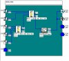
for example
- create bit that tells you that alarm is tripped (this can be B2 if you connect
inverter B5 output to one of the B2 inputs).
- if password is ok disarm system (an arm/disarm function can be simple SET/RESET block)
- turn alarm outputs if alarm is detected AND system is armed (just an AND block)
- an alarm can also be wrong password (doesn't have to be switch or sensor)

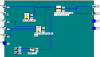
also i would probably use more than one digit password
so each digit would require separate counter. to manage this
i would start by creating some basic functions:
detect long OK press (this arms alarm)
detect long ESC press (this resets all counters and returns to first digit)
detect short ESC press (this increments counter for current digit)
detect short OK press (this initiates check for current digit and switches to next one)
 
panic, about the functions for arming and disarming im not using the long press button, i made it so if u press (OK) twice it arms, and if u press (ESC) once it disarms. I couldnt find out how to do it the long press way, same with short press.

But that part seems to be very easy in comparation with the password system. I still cant make my mind of how could that be assembled using this kind of logic programming.
If you could explain the password method in a more graphic way it prolly be much better.
Thanks for your time, i really apreciate it
 
that is not important, all it matters is that you develop some logic
with clear steps what need to be done. learn about delay one pulse instructions. you will need them to create some of the functions
such as long and short press detection (that's what I would do, but
you can try anything you like). here is simple password logic as start.
it is not developed fully and it is not bullet proof. that's YOUR job.
you have programming manual, software, cable and controller - use them.
i don't want to take fun out of it...
i only tested password entry and comparison and that part is ok.
 

Attachments

  • alpha.gif
    alpha.gif
    123.3 KB · Views: 786
Thanks panic mode, by first look i see it's pretty complex the logic diagram, i'll try to understand how it works and what it does.
I think it will take me a couple of hours to understand all that, i really suck at logic :cry:
 
panic mode, i couldnt figure out what does ur example exactly does, i spent hours trying to "decode" it without help.
In the mean time i tried to do some kind of "steps" password system, and here is what i got:
To arm and disarm the alarm you have to press the (OK) button once and imput the password (UP, RIGHT, DOWN).
What u think about it? Any idea?
 

Attachments

  • screen.png
    screen.png
    30.4 KB · Views: 243
Hola buenas noches!!!!!!

Soy nuevo en este foro.....

Estoy buscando el software CLS (Crouzet Logic Software), estoy recien trabajando con el Xt20 Millenium, pero no tengo el software, ojala que alguien pudiera pasarme un link para bajarlo ok.

Gracias...
 
Status
Not open for further replies.

Latest threads

New Articles From Microcontroller Tips

Back
Top