Code:
list p=16F628A
include "p16f628a.inc"
__config _INTRC_OSC_NOCLKOUT & _PWRTE_ON & _BODEN_ON & _MCLRE_ON & _WDT_OFF & _CP_OFF
org 0x0000
movlw 0x07 ; I think these should also be added
movwf CMCON
bsf STATUS,5
movlw 00h
movwf TRISA
bcf STATUS,5
movlw b'00000101'
movwf PORTA
goto $
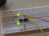
endThose were the codes i used in my PIC16F628A. I have connected the power supply of 5V,2A directly to the PIC as 5V is an ideal voltage. Then i connect the RA0, RA1 and RA2 to 3 leds (Directly connected to the pins without any resistors). However my led is not lighting up. Does anyone know why?
Here is my second problem. I am using pickit2 and i would like to debug the code. I went to the debug and select my device(pickit2). I got an error, This is the screenshot.
**broken link removed**
")
