Continue to Site

Welcome to our site!

Electro Tech is an online community (with over 170,000 members) who enjoy talking about and building electronic circuits, projects and gadgets. To participate you need to register. Registration is free. Click here to register now.

  • Welcome to our site! Electro Tech is an online community (with over 170,000 members) who enjoy talking about and building electronic circuits, projects and gadgets. To participate you need to register. Registration is free. Click here to register now.

Problems with battery power system

Status
Not open for further replies.

vielle568

Member
I have installed a hybrid system consisting of a wind generator and some solar panels to provide energy for my house. The energy is used to charge a bank of twenty 150AH lead acid deep cycle batteries that are connected in series. The batteries have a charge controller with a dump load to ensure that they are not "overcharged" when there is too much wind; there is also a relay to automatically reconnect the house to the electricity company should the battery level get too low. An inverter changes the DC voltage from the batteries and converts it to AC for the house.

Sadly the system does not work correctly; when the batteries are charged up (around 260 volts) and the house is connected it will only have enough energy to run for a couple of hours before the voltage level has dropped to below 250 volts and the system is ready to disconnect. When it was initially set up the batteries would support the house for at least four days without any wind blowing! There's a leak in the system somewhere and I don't know how to track it down.

The batteries seem to charge OK, but slowly. I get the impression that if the charge level drops then the battery voltage actually starts to drop slowly. There's power coming in from both the generator and PV panel cables so the batteries are getting their charge voltage alright.

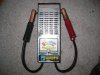
I've checked all the batteries too. Every one is reading 12,XX volts so I can't see any indication of a burnt out cell causing the problem.

The inverter works OK and is not drawing an excessive load; I measured the current flowing in the cable when the inverter had no output and it was taking about 0,8A (it's a 5KW inverter).

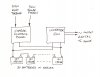
I am getting suspicious about the cables. There are 20 jumper cables connecting the batteries in series; I made these up myself; could these be causing the leak in the system? The cable lugs are bolted to the battery terminals but the cables are soldered to the lugs. Could a poor joint be the cause of such a problem? If so, how can I check out the cables? Any other ideas?

I've included a simple sketch of the system diagram. Thanks for any advice on this subject.
 

Attachments

  • Numériser0006.jpg
    Numériser0006.jpg
    223.1 KB · Views: 153
The voltage drop from the negative terminal lug to the positive terminal lug, of each jumper cable connection, should be approximately zero volts. Using a DMM or other known good voltmeter, measure all the lug to lug voltage drops, using the actual battery terminal lug as the test point. If necessary, scrape the top of each lug down to bright metal, to insure that you have a valid measurement.

If you find a particular measurement that is significantly non-zero, then there is a problem with the quality of the connection. Check any questionable jumper cables to see if they are warm, a result of too much resistance in the connection.

You might also check the cables which connect the ends of the battery chain, by using this method, if it is convenient.
 
Sadly the system does not work correctly; when the batteries are charged up (around 260 volts) and the house is connected it will only have enough energy to run for a couple of hours before the voltage level has dropped to below 250 volts and the system is ready to disconnect. When it was initially set up the batteries would support the house for at least four days without any wind blowing! There's a leak in the system somewhere and I don't know how to track it down.

The low disconnect voltage is far too high and the high disconnect voltage is far too low.

250V is 12.5V per battery, you should be able to safely discharge them to at least 10.5V if they're deep cycle batteries.

You are not charging them up enough either, 260V is just 13V per battery, the recommended float charge for SLAs is typically 13.8V per battery but for a fast charge you should go higher, 14V minimum.

I doubt there's any leak in your system, you're only using a tiny fraction of the batteries' capacity. When the batteries were new they lasted for longer because they where shipped nearly fully charged. Since using them you've only partially discharged them and nowhere near fully charged them.

Consider increasing the upper cut-off voltage to 14V per battery, 280V, you should probably go higher but let's play safe for now. Set the lower cut-off voltage to 11V per battery maximum, 220V, again you could go lower but not fully discharging the batteries prolongs their life.

You'll probably find that the batteries last for much longer. Ideally, look at the datasheet and find out what the recommended charge and cut-off voltages are for the load you're drawing.
 
Last edited:
it will only have enough energy to run for a couple of hours before the voltage level has dropped to below 250 volts and the system is ready to disconnect. When it was initially set up the batteries would support the house for at least four days without any wind blowing!

How much of your 150 A-h @ 240 v = 36 kwh are you now getting? The four days tells me your average draw is 400 w, about half that of the average house.

The equivalent resistance of 20 batteries in series is probably ~0.4 ohms so if you load the string with a 10A load you should see no more than a ~4v drop. A 120v 10A hair dryer probably also runs on DC voltage, so you could check 10 batts. at a time with this.
For more precision add in the resistance of your 20 jumper cables.

Depending on the results of this overall test, you could charge and load-test each battery individually for capacity. One or more could have a bad, sulphated, cell.
 
Last edited:
Hi again,

Read the three parts of the battery university. Focus on charging and discharging Sealed Lead Acid (SLA, VRLA, AGM) type of batteries. I think Hero has it right. During charge, SLA's should be charged using available current till their voltage is 2.45 Volts per Cell (VPC), then the voltage is held constant at 2.45VPC until the charge current drops to a low value, and then you disconnect the charging source, or revert to a long term "float" of 2.3VPC. When discharging, it is ok to go down to 1.8 or so VPC.

I said this before: the best authority on your batteries is the maker. Read their data sheet.

One thing that I dont understand about your system is why doesn't the solar output always feed the house, with only the excess solar output (if any) being used to charge batteries. This is the "bird in the hand" analogy. In other words, if there is a Watt available, it should be used in real time to prevent "buying" that Watt from the power utility, rather than trying to save it as chemical energy for later use... Charging and Discharging later is not as efficient as using the Watt in real time...
 
Last edited:
Hi Everyone,

Thank you all for your feedback.

I can raise the high cut off level to 280 volts, but no higher because the dump load kicks in above this point. The low level cut off at 220 volts is not possible because both the inverter and the charge controller have low battery warning circuits that will disconnect the system should the level get too low. I can go down to around 230 volts, but no lower.

I shall try again to get some info on the batteries from the manufacturers (the last attempt was all in Chinese). I did read the site "Battery University" that you mentioned in a previous message MikeMl and it was here that I was lead to believe that lead acid batteries shouldn't be brought down to less than 2.1 volts per cell. This for me worked out to 252VPC for the 20 batteries and hence my low cut off was set at around 250 volts.

I am still suspicious about the jumper cables and so I'll check them out just to make sure.

The house is small, and at the moment it is in a state of restauration so not all of the electrical system is in operation. The lights function, computer (naturally) fridge, microwave, washing machine and other minor appliances. The overall load is not excessive; maybe 4 or 5 amps maximum. I'll just let the batteries drain lower and see how long it all runs for. As I said, it ran for about 4 or 5 days when first set up about a year ago. I'm sorry Hero999, but the batteries were't fully charged at that time, they were delivered dry without any electrolyte.

I'll keep you posted.
 
... the batteries were't fully charged at that time, they were delivered dry without any electrolyte.

I misremembered the previous thread. Sounds like your batteries are Flooded Cell Lead Acid. They were delivered "dry-charged", and you poured in the acid. In that case, the charge voltage is more like 2.40VPC, and if they are "deep-cycle", the discharge limit is ~1.9VPC.

Note that to fully charge these batteries, the voltage should be allowed to rise to 2.40VPC, at which point the charge regulator is supposed to regulate and hold constant the battery voltage while until the charging current naturally drops to less than an amp or so as the batteries stop accepting charge.

If the charge cycle is terminated upon first reaching 2.40VPC, then the batteries will be only ~75% charged. The remaining 25% charge occurs while the voltage is being held constant. I do not believe you are doing the "hold the voltage constant while the current drops" part of the charging algorithm.

Also, be advised that flooded-cell batteries benefit from a periodic (but infrequent) "equalization charge" as discussed on BU, especially if you terminate the charging process early like you are doing...
 
Hello Again,

Well the batteries are up to around 255 volts and the house is connected. I'll let it run and see how long it goes for before it hits about 230 volts. At this level there's a low voltage warning signal and if I ignore this the system will automatically disconnect.

At the moment here are a few lights on in the house; the current entering the inverter is around 1.8 to 1.9 amps and the current on the cable leaving for the house is around 1.7 amps. This suggests that the inverter is working correctly.

I checked the voltage across all the jumper cables and there was a small pd between the terminals, but the largest difference was 0.8 mV and I doubt it this is really significant (but please correct me if I'm wrong).

I can't find any info on the batteries. The manufacturer doesn't have a site or any datasheets so I can't get much further. I've contacted the vendor for information. Similarly, the charge controller; the "User's Guide" is just a booklet explaining how to connect the panel to the wind generator and the solar panels; it includes no schematic or technical information. The controller seems to control the generator direction and monitor the charge voltage/current and that's about all. I've asked the manufacturer for more details but I've been told that the design is a company secret and they won't disclose any more data! Inside the controller there's basically a pcb that controls the lcd panel the 2 direction relays for the servomotor in the generator. Other than that there's not much else to be seen.

I imagine that it's possible to add some kind of charge regulater to my controller circuit? Could someone possibly direct me to a schematic out there? Thanks!

Vielle568
 
2A @ 800 uV is pretty low resistance. There might be high impedance due to corrosion between the batt. post and the jumper clamp, so called contact impedance.

But I'm more concerned about the internal resistance of the batteries.
A car battery drops from 12v to 4v with a ~400A load so the internal impedance is (12-4)v/400A = ~20 milliohms, but this varies with load current.

You might want to put a moderate load on a few batteries one at a time and check them. You'll pretty soon get an idea of what is normal impedance.

A C/20 rate is commonly used, and this would be (150A-h)/(20h) = 7.5A. 12v/7.5A = 1.6 ohm, about 40' of 26 AWG.
If Vopencircuit = 12v and Vload across the wire = 11v then your int. batt. impedance is R = [1.6(12/11)] - 1.6 = 0.15 ohm.
The exact R value of the wire is not important as long as you test each batt. the same.

BTW, I accidentally unsubscribed from this thread; how to fix?
 
Last edited:
Hi Willbe,
I understand what you're suggesting I do but what I fail to see is the overall result. Why is the internal battery resistance important? Does a battery need a certain resistance to indicate that it is in good condition or fully charged up? Would a low (or high) resistance be an indication of a faulty battery or cell? Could you please explain a little further? Thank you.

Vielle568
 
Does a battery need a certain resistance to indicate that it is in good condition or fully charged up?
Yes.

Would a low (or high) resistance be an indication of a faulty battery or cell?
Yes.
Could you please explain a little further? Thank you.

Vielle568
Thanks, Mike.

A good car battery fully charged cranks the starter motor fast. High Voc and low Rint.

A good car battery low in charge cranks the starter motor slowly but it hangs in there. Low Voc and low Rint.

A bad cell has the starter cranking fast at first and then it slows rapidly, I believe due to internal resistance increasing [maybe with internal heating] and not so much due to open circuit voltage decreasing.
High Voc and increasing Rint.
If the batts weren't sealed you could confirm this with a hydrometer.
A bad connection may have the same effect.
 
Last edited:
Thanks MikeMl and Willbe,

The cells aren't in fact sealed. The batteries were delivered dry and I added the electroyte. Mike suggests that they're flooded cell lead acid batteries. I also have a hydrometer (but I've never yet used the thing), so how do I check out the internal resistance using this?

Vielle5658
 
There are several battery test instruments that actually place a test load across the terminals. If you check with an automotive parts supply store in your area, you will probably find something that is affordable, and will provide a quick check to see if a battery is actually storing the charge. A modestly price unit should cost less than $100 US, and will be sufficient for your purpose.
Be sure to try to charge the battery first before you test it.

I bought this tester for about $50 USD, but that was probably 20 years ago.
It has a power resistor within the upper vent cage. You can feel the heat when the battery current flows through it.
It has a switch, so that you can also test 6 volt batteries under load.
 

Attachments

  • Battery Load Tester.JPG
    Battery Load Tester.JPG
    1.2 MB · Views: 155
Last edited:
Or you could just buy power resistors and test it under load with a multimeter.
 
The wire size I gave you will melt in 27 sec. according to Mr. Onderdonk,
**broken link removed**
so you should go with heavier and longer wire, or else immerse the wire in water. Nobody ever got killed with voltages less than 47v.

Hydrometer readings: You're checking the specific gravity which correlates to the state of charge.
**broken link removed**
Water (a dead cell or fully discharged battery) reads ~1.0. Sulfuric acid and water has a higher specific gravity and so is denser than water.
Battery solution will eat holes in your clothes and it will sting if you have open wounds. It could take a month for the holes to show up.
 
Last edited:
Page 2 of this tabulates the SGs as a function of State of Charge as measured with a hydrometer. You should measure yours; you are looking for general state of charge, and variations from cell to cell.

As to measuring the internal resistance, it is a method of determining the battery's ability to deliver instantaneous current, such as when batteries are used for starting. Since your current is much lower, I would run the battery until it is "discharged" (based on how you operate it), and then measure the SGs and individual battery voltages. The total battery voltage will sag and disconnect your load when the first set of cells become discharged. What you want is all the cells to be the same, so if a given battery in your series string is always the first to go dead, then it is the weakest link in the chain, and should be replaced...
 
Hi Again Everyone,

I mentioned yesterday that the system was set in motion with the batteries at 255 volts and the house connected. The connect/disconnect circuit was unplugged and the system was free to run to the limit. This evening (27 hours later) the voltage had dropped to 216 volts and the inverter was putting out a warning signal that it was about to disconnect. I had to revert back to the national grid.

During the 27 hour period the house has been taking very little power. There's no heating or water heater to draw the amps; just some lights yesterday evening, a small fridge and a microwave at mealtime; nothing else (except the computer). Today was overcast and there was no wind but even so, where's all the power gone?

I contacted the manufacturer to ask for more information about the batteries and the controller. No info on the batteries but I did get some data on the controller; an updated user's guide. It doesn't tell me much but it seems that all the controller does is to control the generator's direction towards the wind. It also monitors the output volts and amps and kicks in the dump load at high wind speeds; but there's no information about battery charge control. It's possible this function isn't even included in the controller design. I've asked the manufacturers to verify this question but as yet they haven't replied.

Maybe if this is the case then part of my problem lies here; I simply need to add an efficient charge controller to my system.

As for the batteries, they're fully drained now so I'll use the hydrometer and check the cells as suggested. The battery bank dropped too fast; there must be something wrong somewhere. I'm off to search....

Vielle568
 
Status
Not open for further replies.

Latest threads

New Articles From Microcontroller Tips

Back
Top