Continue to Site

Welcome to our site!

Electro Tech is an online community (with over 170,000 members) who enjoy talking about and building electronic circuits, projects and gadgets. To participate you need to register. Registration is free. Click here to register now.

  • Welcome to our site! Electro Tech is an online community (with over 170,000 members) who enjoy talking about and building electronic circuits, projects and gadgets. To participate you need to register. Registration is free. Click here to register now.

Problems with a reasonably simple mosfet switch circuit. kinda noob here.

Status
Not open for further replies.

Gigaah

New Member
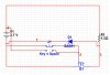
Diagram is attached. Its from multisim(electronics workbench).

The 3.7v voltage is a lithium polymer battery. When the switch is pressed current flows to the 1.5ohm load. My problem is. At some point the load is removed(unscrewed). and a battery charger is screwed in its place. Multisim shows the Mosfet conducts current back to the battery over thru the mosfet. I think this is called "reverse biasing". I really don't want this to happen. I only want the current to flow thru the diode when the charger is attatched. Inline with the mosfet There will be discharge protection for the battery. and inline with the diode there will be charge protection circuits.

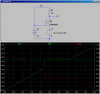
The only way I've been able to test it is to flip the resisitor and the voltage source to test how the mosfet will act with the charger pushing current to the battery in the program. I'm kinda stuck. I can't really use a mechanical switch due to space contraints i'm unable to find a 3amp tactile switch so I thought a mosfet would be the ticket.

Even at that I'm not happy with having to use even a schotty diode to the charge protection at 3.7v even .2 v drop is something I want to avoid. Howver since the fets will conduct when reverse biased I'm not sure how to work it.

Can anyone help straighten me out here?
 

Attachments

  • electro-tech mosfet1.jpg
    electro-tech mosfet1.jpg
    55.3 KB · Views: 456
I think the diode is backwards. It's to protect from reverse polarity?
 
The diode only exist to create a one way channel TO the battery when the load is removed and the charger is put in its place. However the mosfet is causing me problems in that respect
 
All power Mosfets have a parasitic diode from drain to source. In the case of an N-Fet, the diode points from source to drain, so is reverse-biased in the direction the NFet is connected as a switch. However, if you do something to make the source more positive than the drain (the reverse of the normal situation), the parasitic diode becomes forward biased, and the channel conducts, regardless of what you do to the gate.

btw-What is the part number of your Nfet???

Look at this, where the source voltage of the NFet is swept from 0 to 6V. Note the current that flows back into the battery when the source voltage exceeds 4.2V (3.7V battery + 0.5V Vf of the parasitic Schottky inside the FET)/
 

Attachments

  • DF124.png
    DF124.png
    30.3 KB · Views: 357
Last edited:
The mosfet was a genaric virtual fet. Finding the right one in multisim is difficult. multisim also keeps having convergence errors for no reason that it cannot solve even on simple projects.

I guess if that is just how the mosfet operates I'll have to find something else. However thus far i'm just not handy enough to get it done. The only thing I've found is an ideal diode mosfet controller from linear technologies. I really don't want to spend 4-5$ each. https://www.electro-tech-online.com/custompdfs/2010/12/4352fa.pdf

Unless someone can help offer another solution or find me a tactile switch that will handle 3amps and fit inside a 9mm cylinder with the button facing out the side I might not have any choice.
 
Sure, the body diode. I think you still want to turn the diode around.
Well you can always use another diode in the FET path. Or you could use a transistor instead of a FET. Or you might be able to sneak by with a FET with a lousy body diode (high drop) and a ultra low Vf diode like SBR10U60CT.
 
The diode needs removing as it is just bypassing the mosfet. If your trying to stop power flowing back from your load (this does not normally happen) you need to put the diode in series with the mosfet. Can you show us the diagram for your battery charger ?
 
I don't have a diagram for the charger and in my situation even .3v drop from the source to the load is too much.I thought I could avoid this with a mosfet early on but now I realize now the circuit drawn is all wrong and the mosfet won't work like I thought initially it would. However I think I finally found a micro switch that I can squeeze into my 9mm tube with a little work and will handle 3 amps. So I think my situation has been resolved.
 
well if a switch will work fine then why won't the mosfet with no diode ? I think you just need to throw the diode out. is it a bought charger ? if it is i doubt you will have a problem with it feeding current back out
 
since the circuit voltage is so low I'm concerned about the forward voltage drop.
 
Last edited:
Status
Not open for further replies.

Latest threads

New Articles From Microcontroller Tips

Back
Top