Continue to Site

Welcome to our site!

Electro Tech is an online community (with over 170,000 members) who enjoy talking about and building electronic circuits, projects and gadgets. To participate you need to register. Registration is free. Click here to register now.

  • Welcome to our site! Electro Tech is an online community (with over 170,000 members) who enjoy talking about and building electronic circuits, projects and gadgets. To participate you need to register. Registration is free. Click here to register now.

Problem with voltage regulator circuit (smoked cap)

Status
Not open for further replies.

DSGarcia

New Member
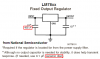
I am using a 7805 voltage regulator to provide +5 volts to a Basic Stamp processor and a matrix LED driver chip. On the input side of the regulator, I have a .33uF 35-volt tantalum capacitor and on the output, I have a .1uf 35-volt tantalum capacitor and a 10uF 25-volt electrolytic capacitor.

I am using a 5 pin connector on my circuit board that provides unregulated +9 VDC (actually more like 12VDC) from a plug-in AC adapter. Also on the cable to this connector are RS-232 Rx, Tx and DTR lines. The power ground and the RS-232 ground signal share a common ground that is tied together.

My circuit was working fine (for a few hours) when plugged into the serial port of my computer used for development and testing. The circuit had problems when plugged into the serial port of another device--it would not run properly, but when unplugged from the serial port, it would work. However, there was no serial data transmitted and the port was idle when it was plugged in. Strange that when plugged into an idle serial port nothing would happen.

I plugged the serial cable back into my notebook computer and it worked fine again. Finally (after several attempts), when plugged into the other serial device, it would then start properly, but after a few moments, some of the smoke got loose. I unplugged it before all the smoke escaped but the circuit was working while it was having a smoke.

The strange thing--it was the .33uF cap on the input of the voltage regulator that smoked. There is no connection between the serial lines and the input power other than sharing the same cable and connector (and the common ground), but there were no shorts obviously since everything worked fine while connected to the PC. The other serial device only had pins 2, 3, and 5 connected so no other pins could possible be shorted by the device.

My wildest thought is that the route of the cable was different when plugged into my serial device. There was an AC power strip mounted under the counter top and a monster of a UPS on the floor below that. Could voltage have been induced into the cable to cause this problem? If so, how can the circuit be protected? I am not certain that is my problem, but I am baffled what else it could be. I was not able to take any voltage readings before I had to leave.

Does anyone have any ideas? I had to leave the equipment at a remote location, but will build a duplicate of the circuit for debugging. What should I look for?

Thanks,
Dale
 
I have had problems with tantalum capacitors exploding when power is applied. So I don't use them anymore, just electrolytics and ceramic discs for power supplies.
 
As AudioGuru mentioned, sometimes tantalums throw a tantrum for no reason.
There was an AC power strip mounted under the counter top and a monster of a UPS on the floor below that.
Was the UPS supplying power at the time? Most UPS's supply a square wave or a pseudo sine wave that, when passed through a transformer and rectified, could possibly spike the tantalums enough to blow them. I would look at the stability of the power source at this point.
 
hi,
It sounds as though you have an open ground/common line in the system, most likely on your psu/pic pcb.

When its working OK, the ground return is along a 'sneak' path, so the system works.

When connected to another device, this sneak path is missing so the system dosn't work.

Tantalum caps are OK, but they will not tolerate more than 0.5V reverse voltage before they self destruct.
If enough reverse energy is available they will explode producing a globule of molten metal.

The fact that the tant cap has burnt out, is again an indication of a open ground line.
Check the PIC pcb, use a ohm meter on ALL the ground lines to ensure continuity.
 
Last edited:
Thanks everyone for the comments.

The circuit was not being powered by the UPS, I just mentioned it being there in case anyone thought a current could be induced into my [unshielded] data cable. The wall plug power supply should have filtered out any effect from a UPS at any rate, should it not? The other serial device might have been plugged into UPS power though.

My parts supplier (Mouser) has only a very limited selection of thru-hole ceramic capacitors but lots of the tantalum which is the reason the tantalum devices were used.

As far as the grounding problem, the blown capacitor was on the input side of the voltage regulator which makes me think the problem was created externally somehow. When the device was plugged into no serial port, it was working (processor functioning and display LEDs on) which shows me that the power ground was working fine. When plugged into the PC serial port, it worked fine. I had two different serial devices with which I had problems, but the serial ports worked fine with other equipment which showed the serial ports were also working fine. This is what is so confusing to me and led me to believe it was induced current from the different physical routing of the data cable (about 15 meters long, but semi-coiled on the bench).

Examining the Basic Stamp, there appeared to be no indication of damage. The only other noticable damage was the 10uF cap on the output of the voltage regulator, but it appeared that it was from the smoke residue from the blown .33uF cap on the input (the 10uF cap was vertically above the smoking part).

I intend to build another unit for testing. Other than changing to a ceramic cap on the input side of the regulator, is there anything else I should consider or check? Should I also put a 10uF electrolytic on the input of the voltage regulator (the data sheet only showed the .33uF)? One other problem is that I can only get a .1, .22, or .47 in the ceramic--which do I use--the data sheet shows a .33uF on the input side?

Do I need a reversed diode in parallel with the capacitor to eliminate any reverse voltage--perhaps caused by frequent plugging in and out from the power?

Thanks,
Dale
 
I agree with Audioguru, don't use tantalums - as far as I'm concerned they are far too unreliable, you don't see them used in domestic electronics anymore for that reason.
 
Nigel Goodwin said:
I agree with Audioguru, don't use tantalums - as far as I'm concerned they are far too unreliable, you don't see them used in domestic electronics anymore for that reason.

wow, England and Europe must be way different than the US. Electronics around here are filled with little tantalum caps. Some real high end stuff uses the new organic polymer electrolytic caps, but as far as I've, those caps are very expensive even in quantity.

I guess most of the electronics I work with daily are computer related, perhaps that type of cap is unique to the industry?
 
Texas Instruments say to use a 0.33uF input capacitor but National Semiconductor say to use a 0.22uF. They say to use a ceramic disc output capacitor so the input capacitor is also probably the same. Use the 0.22uF ceramic disc from Mouser as the input capacitor and it will be fine.
 

Attachments

  • LM78xx regulator capacitors.PNG
    LM78xx regulator capacitors.PNG
    14.7 KB · Views: 381
You do know that tantalums have their stripe on the positive end, and electrolytic caps have their stripe on the negative?
 
I've never had a reliability problem with tantalum caps, but in the early 1980's there was a war or cartel or something that made them scarce and expensive.

Even today, they usually aren't the cheapest way to provide capacitance, and IMO this is why you don't see them in consumer goods. The products I'm involved in have to be extremely reliable, and we have no problem using tantalums.
 
Tantalum capacitors are quickly damaged by high surge or ripple currents so you need to be careful using them in power supply circuits. If you use one at the input of a regulator it's a bad idea to connect to a power supply that is already switched on with it's output caps fully charged, the surge can kill the tant. and it will fail shorted hence the smoke. I too have never had any reliability problems with tantalum capacitors, I've been using them in power supply circuits and everywhere else for 30 years with good results. Just watch the ripple currents and don't get too close to the maximum voltage rating.
 
I did not realize there were problems with the tantalum caps. Mouser has pages and pages of them and only a very small selection for the ceramics (of the radial leaded type). I used what was common because that was what it appeared that everyone else used (judging by the number of different part numbers).

I was not aware that they had a polarity, but looking closely at a good part, there is a single narrow long stripe down one side. This could be the source of my problem though it did run a couple of hours or more with +12VDC input with no problems. Would it have lasted this long if the polarity were the problem?

This still does not answer my problem why it appeared to work plugged into my notebook serial port or unplugged from a serial port altogether but then the display would not work when plugged unto a different serial device.

Thanks,
Dale
 
Brevor said:
Tantalum capacitors are quickly damaged by high surge or ripple currents so you need to be careful using them in power supply circuits. If you use one at the input of a regulator it's a bad idea to connect to a power supply that is already switched on with it's output caps fully charged, the surge can kill the tant. and it will fail shorted hence the smoke. I too have never had any reliability problems with tantalum capacitors, I've been using them in power supply circuits and everywhere else for 30 years with good results. Just watch the ripple currents and don't get too close to the maximum voltage rating.

When I was writing my post, I did not have yours yet. Perhaps this explains the smoke because I did plug the DC power plug in and out (while the AC adaptor was plugged in) several times while trying to see what was going on. Would a .22uF ceramic cap work as suggested above because due to the nature of the installation I do want the ability to plug DC power in while the AC adaptor is plugged into the wall?
Thanks,
Dale
 
Replace the tantalum capacitors with ceramic discs.

Mouser sells many tantalum capacitors and only a few ceramic ones because of PROFIT! Tantalum capacitors are a ripoff.
 
It would probably be Ok but I would just use a plain old electrolytic, See the following application note as to why a high value ceramic cap may not be the best for this application either.


**broken link removed**
 
Mouser sells many tantalum capacitors and only a few ceramic ones because of PROFIT! Tantalum capacitors are a ripoff.

Aw come on $crooge I know your way too smart to really believe that.
Engineers are constantly pushed to design the product at the lowest cost, No competent engineer would use a more expensive component where a lower cost one would work just as well. Tantalum capacitors have their place in circuits where their specific properties can be used to full advantage. Thats why there are so many different types of capacitors. A good engineer knows what type of capacitor to use for a given type of circuit. In some circuits tantalums are the best way to go, other times they are not. Engineering is knowing the difference.
 
Last edited:
I used many expensive and small tantalum capacitors in the 70's. Some exploded. I haven't used one since about 1980.

I hardly ever cut costs on my projects at work. They were extremely expensive (selling price) custom-made circuits, usually only one, that won the contracts because no other company could do what I could do.
The head offices of huge Canadian banks wanted the very best communications systems. The government (they are crazy) wanted the airports to have FM broadcast-quality PA. I did it.

The biggest ceramic disc capacitor I have ever seen is 1uF. The article about them causing voltage transients used 22uF.
 
The engineers might want to reduce component costs IF it doesn't involve a sacrifice of performance, but if suppliers can sell caps for 10x what they are actually worth because people think they are better than the cheaper ones then they will!
 
hi,
The tantalum capacitor is like any other electronic component, if the circuit its in is designed correctly, they work trouble free.

I know that tantalums are more expensive than electolytics, but their stabilty, frequency characteristics, leakage and size are superior to electrolytics.

As a choice, I prefer tantalum capacitors, but I do use large electrolytics for smoothing applications.

Look at the *.pdf
 
Last edited:
mneary said:
I've never had a reliability problem with tantalum caps, but in the early 1980's there was a war or cartel or something that made them scarce and expensive.

Even today, they usually aren't the cheapest way to provide capacitance, and IMO this is why you don't see them in consumer goods. The products I'm involved in have to be extremely reliable, and we have no problem using tantalums.

I think the problem in the 80's was possibly due to reliability?, in the late 70's early 80's consumer electronics were stuffed full of tantalum capacitors - then they started suffering massive failures, as a result they were phased out and have rarely appeared since. From a servicing point of view the occasional use of tantalums was a plus point - whenever I see one it's the first thing I check, and usually replacing it will cure the fault.

Perhaps consumer items used lower grade tantalums?, I've no idea, but there are VERY few applications I'd use one in - the timing capacitor in a 555 circuit would be one, where they are MUCH better than electrolytics.
 
Status
Not open for further replies.

Latest threads

Back
Top