TheEngineer
New Member
Hello,
For a project I am attempting to make a solar tracker that tracks the sun throughout the course of a day from east to west. I will have circuitry to sense the sun and then use a motor and linear actuator to adjust a PV panel to face directly at the sun.
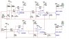
The circuitry uses photoresistors (along with an LM339 comparator) that will change resistance depending on the amount of sunlight. Therefore, when the West sensor sees more light than the East, it will have less resistance and allow for more current to flow and activate a motor relay to turn the panel towards the West. When the panel is directly under the sun, both sensors will see equal light and the panel is not moved. At the end of the day, when both panels see equal darkness (high resistance), the panel will move back to the East.
I found several schematics online for the control circuitry but am having trouble getting the design to simulate correctly (using MultiSim). I can configure the circuit to work correctly for one instance (i.e. pointed directly at sun or with the West seeing more sunlight), but it does not work when I change resistances.
Basically, when the circuit sees equal light, the photoresistors will have a value of approx 10k. In order for the panel to stay where it is, the voltage at the base of each of the transistors needs to be high (the actual motor relays will connect to the collector of the xistors).
Similarly, the base voltage of the EAST_DRIVE xistor needs to be high when the WEST resistor is 10k and the EAST is 100k (dark) so that the panel will turn towards the West.
The problem I am seeing is that since the outputs of U3D and U3B are tied together, that node will only be high when both outputs are high. For whatever reason, I cannot get the values to come out right.
I am attaching a jpg of the schematic as well as the MultiSim file (in zip folder) incase anyone can maybe run the simulation and see if they can find out what is wrong? I have been racking my brain trying to troubleshoot this.
Thanks!!
For a project I am attempting to make a solar tracker that tracks the sun throughout the course of a day from east to west. I will have circuitry to sense the sun and then use a motor and linear actuator to adjust a PV panel to face directly at the sun.
The circuitry uses photoresistors (along with an LM339 comparator) that will change resistance depending on the amount of sunlight. Therefore, when the West sensor sees more light than the East, it will have less resistance and allow for more current to flow and activate a motor relay to turn the panel towards the West. When the panel is directly under the sun, both sensors will see equal light and the panel is not moved. At the end of the day, when both panels see equal darkness (high resistance), the panel will move back to the East.
I found several schematics online for the control circuitry but am having trouble getting the design to simulate correctly (using MultiSim). I can configure the circuit to work correctly for one instance (i.e. pointed directly at sun or with the West seeing more sunlight), but it does not work when I change resistances.
Basically, when the circuit sees equal light, the photoresistors will have a value of approx 10k. In order for the panel to stay where it is, the voltage at the base of each of the transistors needs to be high (the actual motor relays will connect to the collector of the xistors).
Similarly, the base voltage of the EAST_DRIVE xistor needs to be high when the WEST resistor is 10k and the EAST is 100k (dark) so that the panel will turn towards the West.
The problem I am seeing is that since the outputs of U3D and U3B are tied together, that node will only be high when both outputs are high. For whatever reason, I cannot get the values to come out right.
I am attaching a jpg of the schematic as well as the MultiSim file (in zip folder) incase anyone can maybe run the simulation and see if they can find out what is wrong? I have been racking my brain trying to troubleshoot this.
Thanks!!
")

