Continue to Site

Welcome to our site!

Electro Tech is an online community (with over 170,000 members) who enjoy talking about and building electronic circuits, projects and gadgets. To participate you need to register. Registration is free. Click here to register now.

  • Welcome to our site! Electro Tech is an online community (with over 170,000 members) who enjoy talking about and building electronic circuits, projects and gadgets. To participate you need to register. Registration is free. Click here to register now.

Problem with a current mirror

Status
Not open for further replies.

PGrogan

New Member
Hi,

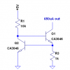
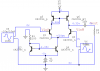
I am trying to simulate this circuit. The circuit is working well but for the current mirror made from two NPN. We consider Vbe = 0,7V for calculation. β=290. I want a current Iout of 675µA. When I simulate the circuit, I get my 675µA on the reference but my Iout is approximatively 840µA. I don't understand what is happening. I tried to simulate the current mirror only with a 300Ω load between collector of Q4 and ground but I seem to get the same problem. Someone has an idea of what is not working?

Thanks!
 

Attachments

  • current_mirror.PNG
    current_mirror.PNG
    24.9 KB · Views: 413
In fact, i thought my circuit was working well. I juste realized that my amp has a differential mode gain Avd = 4,5 in simulation... it should be like 300 in my calculation! Is it my simulator or I am doing something wrong?
 
In fact, i thought my circuit was working well. I juste realized that my amp has a differential mode gain Avd = 4,5 in simulation... it should be like 300 in my calculation! Is it my simulator or I am doing something wrong?

So if I read your simulator correctly, it says you have a collector voltage of about 4.3V on the output leg. That leaves about 0.7V of headroom at the Q point, before it hits the 5V rail. Hardly a good design, being that you have split power supplies. If what you say is true, and you have a calculated gain of 300, with a 10mV input, the output should swing 3V. That's not going to happen when you have only 700mV of headroom, right?
 
Hi!
Nope it isn't! In fact, that is not my design! My problem is that it doesn't saturate. My amp is giving me a gain of about 12. Maybe I have made a mistake in my calculations. I'll check that and I'll repost ;)

Thanks
 
The 1k load resistor is killing the gain. Measure the gain without the 1k resistor.
 
Is it? I don't understant the effect of the load on the gain... It sounds like I am missing something stupid... thanks!
 
The voltage gain of a transistor is the collector resistor value divided by the emitter resistor value.
The load is assumed to be an extremely high resistance so it is not in parallel with the collector resistor which reduces the gain.

This circuit has a current source transistor instead of a collector resistor. It has an extremely high resistance. But the 1k load resistor shorts it and severely reduces the gain.
 
The NPN current mirror is unbalanced because the reference transistor is running with Vce=0.6V, while the output sink transistor has Vce≈4.4V. Beta is higher at 4.4V than at 0.65V.
 
Ok! So if I add polarisation on base of Q1 and Q2 to be sur that Q4 operates near Vce = 0,65 V, I will get a balanced mirror current right?
 
Last edited:
Ok! So if I add polarisation on base of Q1 and Q2 to be sur that Q4 operates near Vce = 0,65 V, I will get a balanced mirror current right?
You need a higher impedance current source (your present one is not very high, so the current changes as the voltage changes).
See below.
Note: This circuit will have a higher change in current vs temperature, which probably won't be a problem in your circuit.
 

Attachments

  • current sink sch.PNG
    current sink sch.PNG
    5.7 KB · Views: 357
You need a higher impedance current source (your present one is not very high, so the current changes as the voltage changes).
See below.
Note: This circuit will have a higher change in current vs temperature, which probably won't be a problem in your circuit.

yes, a Widlar current source would be my choice.
 
yes, a Widlar current source would be my choice.
I don't know if you are implying that the circuit I posted is a Widlar Current source. It isn't, although a Widlar current source is an improvement on the original one used by our OP. It also isn't a Wilson current source. I'm not sure what it's called. I generally call it a feedback current source, or sink (it's not a current mirror). I have used it many times.
 
I don't know if you are implying that the circuit I posted is a Widlar Current source. It isn't, although a Widlar current source is an improvement on the original one used by our OP. It also isn't a Wilson current source. I'm not sure what it's called. I generally call it a feedback current source, or sink (it's not a current mirror). I have used it many times.

No, I meant I would use a Widlar.
 
I don't know if you are implying that the circuit I posted is a Widlar Current source. It isn't, although a Widlar current source is an improvement on the original one used by our OP. It also isn't a Wilson current source. I'm not sure what it's called. I generally call it a feedback current source, or sink (it's not a current mirror). I have used it many times.
Il make a traduction from French : it is called a Base-Emitter Referenced Current Source...
 
Status
Not open for further replies.

Latest threads

New Articles From Microcontroller Tips

Back
Top