Continue to Site

Welcome to our site!

Electro Tech is an online community (with over 170,000 members) who enjoy talking about and building electronic circuits, projects and gadgets. To participate you need to register. Registration is free. Click here to register now.

  • Welcome to our site! Electro Tech is an online community (with over 170,000 members) who enjoy talking about and building electronic circuits, projects and gadgets. To participate you need to register. Registration is free. Click here to register now.

Problem with 433.92 fm transmtter & receiver circuits

Status
Not open for further replies.

james120479

New Member
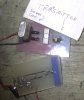
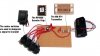
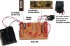
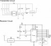
I'm trying to construct a simple transmitter and receiver, where the receiver can recognise numerous transmitters. I've made the circuits using the RF600 encoder and decoders but can't get them to work. I've tried both AM and FM transmitters.

I'm certain the circuits are working, for some reason the transmitter won't transmit. I've made the circuits on copper strip board and have been told this may be the problem and should try cutting the strips so they don't travel the full length of the board. I have tried this but they still don't work. I'm using 3 AA batteries which gives 4.5 volts power, they are low power radio circuits and im wondering if the power source may be a problem (too much/little current?).

If anyone may be able to help me, i would be extremely grateful,

Many thanks,

James
 
A schematic or picture would help. Look at the transmitter and receiver that I use, I bought them from Q Kits. The antenna is by Yageo, available from www.mouser.com. The upper board is the transmitter and signal generator, the lower board is the receiver, shown upside down to show the antenna. The range is in excess of 300 feet.
 

Attachments

  • xmit_rec.jpg
    xmit_rec.jpg
    75.7 KB · Views: 718
If you are using pre-built radio modules, then the layout isn't at all critical, there's no RF involved in the layout - it's all on the modules.

I've used veroboard for RF modules without any problems, try monitoring the output of the receiver with a voltmeter, while you toggle the input line to the transmitter high and low, you should see the receiver output follow the transmitter - but only to some extent, you can't receive a long high level.
 
I have photos of my connected circuits and the original citcuit diagrams, however i am a bit of a novice and i'm having trouble inserting them into this message Is it possible to display jpegs?

**broken link removed**

I've tried the above but i'm obviously doing something wrong :oops:
 
I've measured the voltage at the output of the transmitter and the input to the receiver. The voltage does go high at the transmitter end (from around 3V to 4V) but there's zero voltage on the receiver end either when a signal is transmitted or not.
 
i think i've worked out how to add the images now, the only difference with the transmitter circuit now is that i have added the BC848 transistor since these photos were taken, i'm almost 100% certain the circuits are connected correctly as the chip flashes the led to say its transmitting and at the receiver end the LED lights to indicate it is waiting for a transmission. But no signal is received.

Does anyone have any ideas as to why this may not be working?
 

Attachments

  • transmitter_657.jpg
    transmitter_657.jpg
    61.4 KB · Views: 649
  • receiver_circuit.jpg
    receiver_circuit.jpg
    80.7 KB · Views: 725
  • rf600.jpg
    rf600.jpg
    31.9 KB · Views: 761
Is it possible to test whether the receiver circuit is working? I think the transmitter's working as the antennae pin voltage rises when a transmission is attempted
 
There is not enuf info at the RF solutions website, but I think there should be a DC level at the data output when an unmodulated RF signal is received. What are you using for an antenna? There is none shown in the photo.
 
I've tried using a piece of straight wire on each circuit at a length of 17.5 cm, this is what is recommended for testing purposes in the data sheets.

I am unable to test the data output level at the moment as i'm not with the circuits but i'm sure last time i tried there was zero voltage on all outputs
 
Status
Not open for further replies.

Latest threads

New Articles From Microcontroller Tips

Back
Top