Continue to Site

Welcome to our site!

Electro Tech is an online community (with over 170,000 members) who enjoy talking about and building electronic circuits, projects and gadgets. To participate you need to register. Registration is free. Click here to register now.

  • Welcome to our site! Electro Tech is an online community (with over 170,000 members) who enjoy talking about and building electronic circuits, projects and gadgets. To participate you need to register. Registration is free. Click here to register now.

problem in designing LC oscillator

Status
Not open for further replies.

nesbit91

New Member
Hi guys.
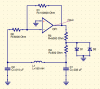
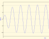
I want to design a LC oscillator. The input is 24 V DC. The output I want to be is a sinusoidal voltage with 4 KHz frequency. I simulated the circuit in Pspice, and the voltage of capacitor become a sinusoidal voltage, but 40e-21 V !!!!! and the output of OP AMP is 10 VDC.
Please, if someone knows help me. Maybe I am making a funny mistake, or missing something.
I really need this, and I don't know what to do.
Thank you very much…


schematic.jpg
pspice.jpg
Capacitor output.jpg
op amp output.jpg
 
The opamp is biassed to work with the inputs and output centred at 0V, but you have no negative supply. The basic circuit uses dual supplies.

Try adding a voltage divider, two equal resistors across the supply and a capacitor from the junction to negative/ground.
That gives you a mid-supply bias voltage, so the opamp output can swing both positive and negative of that voltage.

Then connect the two grounds shown in the basic oscillator circuit (R1 and the LC network) to that point.


Thank you very much. I'll check it now.
another problem that I have, is the voltage of capacitor and inductor is very very low!!! 40e-21 volts!!!! is this normal ???
Merci for your reply...
 
you are missing a connection, the output of the opamp needs to connect to the feedback resistors - R2 and unnamed in the first poorly drawn picture.
 
you are missing a connection, the output of the opamp needs to connect to the feedback resistors - R2 and unnamed in the first poorly drawn picture.

Thank you.
That's right.
I should simulate the circuit part by part. one part for oscillator and one part for amplifier.
My major problem is that why the voltage of LC is so LOW?!!!!
 
The LC tank willl not oscilate by itself, you need to simulate it as a whole. It didn´t simulate properly beacuse the output of the opamp was pegged at the positive supply rail. You need dual supply cca +/-15V for it to run correctly, as you were already told in post #2.
 
The LC tank willl not oscilate by itself, you need to simulate it as a whole. It didn´t simulate properly beacuse the output of the opamp was pegged at the positive supply rail. You need dual supply cca +/-15V for it to run correctly, as you were already told in post #2.

Thanks very much.

I did what you told me, and it is working. In orcad, I connected +vcc and -vcc to the opamp.
But in my real circuit, I don't have +12 and -12 volt supply. I have just one +24 volt and ground. rjenkinsgb in post #2 explained what to do for negative supply, but actually I couldn't draw the circuit he said.
For amplifyig the signal , is there a simpler and better solution, for example using transistors?


Thank you for sharing your wisdom with me. I really appreciate that.
 
If you only have 24V, then you have to use a virtual ground to get it to work. Use two resistors to make a voltage divider to get half of the power supply, then use an opamp as a buffer. Use the output of that buffer as your ground reference - connect bottom end of R6 to it, and take the output between the oscillator and this reference ground.

What is your actual goal with this circuit?
 
It's simply two resistors in series across 0V & 24V to give a 12V point.

That then becomes the "signal ground" as far as the opamp inputs (not power) are concerned. Relative to that, the opamp supply voltages are then positive and negative 12V, giving the maximum possible signal range.

For some applications you can just use the two resistors and a capacitor from the centre point to negative.

For more complex things or where a circuit puts any significant load on that point, and additional opamp can be used as a buffer, as Kubeek says.
 
If you only have 24V, then you have to use a virtual ground to get it to work. Use two resistors to make a voltage divider to get half of the power supply, then use an opamp as a buffer. Use the output of that buffer as your ground reference - connect bottom end of R6 to it, and take the output between the oscillator and this reference ground.

What is your actual goal with this circuit?

Thanks again.
I want to design an inductive proximity sensor. The first thing to do is to make an oscillating signal in one inductor, to make an electromagnetic field. In presense of a metal, because of eddy current losses, the amplitude of the signal reduces. So, by measuring the amplitude of signal, the cirucuit recognizes if a metal is near sensor.
So , in the first step, I want to make an oscillating voltage.
Unfortunatelly, my electronics is not very good. The questions I ask may be funny!
The solutions you offered to me, is it possible to draw them on paper and send it? I didn't understand exactly how to use buffer and it's connections.
Merci...
 
It's simply two resistors in series across 0V & 24V to give a 12V point.

That then becomes the "signal ground" as far as the opamp inputs (not power) are concerned. Relative to that, the opamp supply voltages are then positive and negative 12V, giving the maximum possible signal range.

For some applications you can just use the two resistors and a capacitor from the centre point to negative.

For more complex things or where a circuit puts any significant load on that point, and additional opamp can be used as a buffer, as Kubeek says.

Thanks.
I'm really confused !!!! Sorry!!!!!
I try to draw what you said, I wish I can make it...
I know, you may be laughing at me for not understanding this! I try to get it.
Thank you very much
 
Also, if you switch to LTspice instead of orcad, you will get better support from the members beacuse ltspice is a free simulator and most people here use it. Then you can directly post your .asc file and people can tweak your circuit and send it back to you.
 
THis was done in the old Betamax VCR's - VHS detected the end of tape by having a clear portion at each end, and shining a light through it to a sensor. But Betamax used metal tape at the end and a critically adjusted oscillator with the coil close to the tape - on early models you had a preset resistor which you adjusted so it was 'just' oscillating and when the metal part crossed the coil it stopped the oscillator, and provided an logic signal output.
 
Also, if you switch to LTspice instead of orcad, you will get better support from the members beacuse ltspice is a free simulator and most people here use it. Then you can directly post your .asc file and people can tweak your circuit and send it back to you.
Ok, that's good.
I'm gonna install it, and simulate the circuit on it. Hope I can do this BIG PROJECT!!!!! :)
 
I don't think anyone's mentioned it yet, but if you want to get a sine wave out of your circuit, then you'll need to incorporate some kind of automatic gain control. If you don't, then the net positive gain around the feedback loop will cause the amplitude to increase until it hits the power supply limits, and you'll end up with a square wave.
 
THis was done in the old Betamax VCR's - VHS detected the end of tape by having a clear portion at each end, and shining a light through it to a sensor. But Betamax used metal tape at the end and a critically adjusted oscillator with the coil close to the tape - on early models you had a preset resistor which you adjusted so it was 'just' oscillating and when the metal part crossed the coil it stopped the oscillator, and provided an logic signal output.
Wow, that's interesting!
I never though this kind of sensor is used in a tape!!!!
 
Another problem I noticed is that while the resonant frequency of your LC tank is close to what you're looking for, the ratio of capacitance to inductance is too high to be practical. In an LC resonant circuit, the energy stored in the tank alternates from the capacitor to the inductor every half cycle. The peak energy in the inductor is:
E=0.5*L*i^2
where i is the peak current.
The peak energy in the capacitor is:
E=0.5*C*v^2
where v is the peak voltage.
Combining the two we get:
i/v=sqrt(C/L)
With your component values, the right side of the equation becomes sqrt(10e-6/100e-6) = 0.316
So then
i/v=0.316
or
i=0.316*v
In order to get a 12 volt sine wave across the tank, you would have to have nearly 4 amps circulating in it. That 4 amps has to come from somewhere, and that op amp certainly won't be able to supply it.

You need to make the inductance much larger, and the capacitance much smaller. More suitable values would be 100mH for the inductor, and 0.01µF for the capacitor.

Edit:
I threw this together in a hurry, but you could give it a try in LTSpice.
Colpitts_4kHz.JPG
 
Last edited:
Another problem I noticed is that while the resonant frequency of your LC tank is close to what you're looking for, the ratio of capacitance to inductance is too high to be practical. In an LC resonant circuit, the energy stored in the tank alternates from the capacitor to the inductor every half cycle. The peak energy in the inductor is:
E=0.5*L*i^2
where i is the peak current.
The peak energy in the capacitor is:
E=0.5*C*v^2
where v is the peak voltage.
Combining the two we get:
i/v=sqrt(C/L)
With your component values, the right side of the equation becomes sqrt(10e-6/100e-6) = 0.316
So then
i/v=0.316
or
i=0.316*v
In order to get a 12 volt sine wave across the tank, you would have to have nearly 4 amps circulating in it. That 4 amps has to come from somewhere, and that op amp certainly won't be able to supply it.

You need to make the inductance much larger, and the capacitance much smaller. More suitable values would be 100mH for the inductor, and 0.01µF for the capacitor.

Edit:
I threw this together in a hurry, but you could give it a try in LTSpice.
View attachment 118338

Hi Bob. Thank you.
The explanation of the formulas was perfect...
With these parameters of capacitor and inductor, the frequency becomes 5 KHz, and that's good.
It's a big challenge for choosing the appropriate inductor and capacitor.
In the inductive proximity sensor, the sensivity of sensor and the distance it can sense the metal, depends on the electromagnetic field produced by the inductor, which depends on the inductance, current and size of the inductor. I think I should testimate with different inductors in real to get to the goal I want.
Is there formulas to get to the relation between inductor, size of inductor, current and distance? That's very complex, I know!!!
By the way, the kind of metal, thickness and size of it has effect on the sensivity of sensor.

Thank you, it became a long question!!!!
 
Since I brought up the problem of distortion and gain control a few posts ago, I felt responsible for addressing it. Attached is a schematic for the Colpitts oscillator that I previously posted, but with a diode limiter added. If a diode limiter is inserted in the proper place in the feedback loop, it will accomplish nearly the same thing as a fancy AGC circuit, but with far fewer parts (unless you happen to have the perfect light bulb at hand). The output pic shows a fairly clean sine wave. Output amplitude is dependent on the ratio of the feedback resistors R1/R2.
 

Attachments

  • Colpitts_4kHz.png
    Colpitts_4kHz.png
    39.3 KB · Views: 227
  • Output2.png
    Output2.png
    16.9 KB · Views: 216
Status
Not open for further replies.

Latest threads

New Articles From Microcontroller Tips

Back
Top