Bounty Hunter: Hmm. I think you may be right. I didn't give it a thorough workout on fast transients. I was concerned about the charge rate and drew up an idea with a booster transistor. I should have continued on and tried it to see how that would go, but it seemed fast enough (in terms of 20KHz response, not transients which I failed to test because I just wanted to get this design over with).
I did try a different circuit similar to the one you showed, with a 2nd op amp in the feedback path. The article I got it from warned of the possibility of instability. I tried it and it didn't seem to work so well - a bit of oscillation and serious high-frequency roll off - most likely because I wasn't using the best op amp for the job.
I certainly understand the concern about slew rate and detecting transient signals, but I was thinking that would be impractically fast...oh wait, I thought I read 500 nano seconds! OK, 500micros is significant for audio...nevermind.
 ANYWAYS...
I couldn't get the idea out of my head about using a comparator circuit, so I gave it another go. This time I stopped fooling around with slow op amps and wanted to grab a TL074. Didn't have any so I used a TL084. Pretty much the same thing, both fast and slew-y. I also wanted to try an LM339 but out of them also, found a similar two-comparator chip the LM393 I was going to try. Also quite similar to the '339.
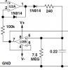
View attachment 98621
Being as lazy as I am, I started out the breadboard circuit just using the TL084 as a comparator, but set up a PNP output that literally DUMPS more than 100mA into the cap (Tim "the tool man" Taylor would be proud). It was still 1uF because I just wasn't getting the hold time with 0.1uF. The other nice thing about the TL084 is the JFET inputs sip so little current, great for the holding cap which is potentially drained by 2 op-amp inputs, and the input buffer. Not sure how well the '84 would work as a comparator, I did have the LM393 on standby duty.
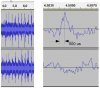
The performance of this circuit worked so well I had no reason to introduce another LM393 package and it's typical pull-up resistor. It responded within a few percent or so from 20 Hz to 20,000 Hz at the full 24 volt pk-pk signal input. This pix shows a single transient input at 22.8 volts pk-pk, and the resulting output immediately jumps up to about 12 volts within about 100μSec. You can even see how it caught that little hump before the scope even triggered.
View attachment 98617
This next pix shows the response when a 2KHz signal was switched up +20dB. It even caught most of that single little spike before the sine waves get big. I don't have pix of it, but this same response showed itself through the full 20 - 20K range.
View attachment 98618
Here I test the overall peak hold with a small burst of 2K. It settles out completely within 2 seconds. That was using a 1 Meg Ω bleed on the 1μF cap. I wanted more.
View attachment 98620
With a 4.7 Meg Ω bleeder resistor, I get about 5 seconds before the meter settles out. In my application, the next -3dB LED will switch about 8/10 second later at about 8.5 volts.
View attachment 98619
So forget all I said about the previous circuit. That one was crap. By comparison, this newer circuit uses the same 3/4 of a chip package, but uses 3 less diodes, a smaller (and non-electrolytic) capacitor, two less resistors, all in exchange for a single jellybean transistor.
Thanks again for all you helpers! ...and NO, this is NOT an April Fools joke!

")