Continue to Site

Welcome to our site!

Electro Tech is an online community (with over 170,000 members) who enjoy talking about and building electronic circuits, projects and gadgets. To participate you need to register. Registration is free. Click here to register now.

  • Welcome to our site! Electro Tech is an online community (with over 170,000 members) who enjoy talking about and building electronic circuits, projects and gadgets. To participate you need to register. Registration is free. Click here to register now.

Precision Rectifier...what's going on here?

Status
Not open for further replies.
upload_2016-3-24_11-30-20.png
 
Why are you are using MANY parts instead of using an LM3915 bar graph IC? It drives 10 LEDs with regulated current as a bar or as a moving dot. It costs $3.89 at Digikey today and is still made in an old fashioned though-holes DIP package.
35 years ago I made a VU meter with two LM3915 ICs in series for a range of 60dB. 10 years ago I used one plus a level detector and a range of 50dB. I made a half-wave peak detector simpler than your complicated one that has many duplicated parts.

Here is my simple peak detector:
 

Attachments

  • peak detector.PNG
    peak detector.PNG
    16.2 KB · Views: 1,076
the file loader here can't find a JPEG sitting on my desktop, so I guess I can't load the schematic.
Hy bounty,
The problem of the file uploader not being able to find image files on a PC is normally due to 'Adobe Flash Protection Mode' being enabled in your browser.
I don't know about other browsers, but to fix this in Firefox:
Tools>add-ons>Plugins>left click on 'Shockwave Flash> more>uncheck Énable Adobe Flash protected mode'

spec
 
Why are there two circuits in series...
The schematic is a fluid document - I keep changing it as I evolve the idea. The first stage was once a full-wave rectifier, followed by a buffer amp to drive the capacitor.
I changed it to a 1/2 wave rectifier and now I guess it looks a little silly there. I then put in a rectifier on the 2nd stage buffer and the 2nd diode to keep it from going full negative (I'm looking for speed.
That is why the resistor values are pretty low.) R29 is used to improve thermal tracking of the op-amp. The general idea is to make it equal to the parallel inputs of the inverting input.
I see now that I put that last diode in, there is a negative "leak" that would drain the cap.

No question this still needs work! It will certainly be simplified by the time I'm done.

Thanks Guru! I like the idea of the transistor acting as the rectifier. I might just borrow this design. I saw a similar idea here:
XTOR SLEW Dual_Polarity_Peak_Detector_EDN_May_12_1994.jpg

As for why I am not using a bar driver chip: $3.89 each from Digi-Key X 16 channels and a few more prototypes = $78 plus shipping. I don't think Mouser even carries them - a sign that the part may be
hard to find in the future. I think I can do better than that. Two LM224 + One MC33079 = $1.36, saving me $2.53 each or apx $50 for all channels.
Sure, there's a few pennies in resistors and PCB space, but I'm not looking in that much detail right now.

One of my guiding principles of engineering is to make stuff work well and be as affordable as possible. I could buy a known-good 16 channel preamp for about $1000 or more, but where's the fun in that?
Cost is an issue. I'm putting most of the $$ into the audio-path capacitors and other important stuff. Power consumption is not an issue, and size/space is not an issue for this design.
 
If the inverting inputs to U1 were 2M ohms then without using 1M for R29 would produce an output error of 0.8V over a wide temperature range. But since the resistors are 1000 times less then the offset voltage with or without R29 is only 0.8mV which is nothing.

I am not a billionaire like the leader of North Korea but I find most electronic parts as being very inexpensive. The last time I bought an LM3915 I paid $1.00 which could buy 2 litres of gasoline.
 
I'm taking your audioguru advice. I'm fiddling with it now, sacrificing speed a bit by using higher resistances to help the cap drain issue, looking into a transistor current source to drive the cap. Of course I nuked the extra stage.
I thought I'd look around for a higher speed transistor, only to find the very affordable 2N3904 is about as fast as you can get for pennies. Anything better is closer to a dollar.
I took the lowly '3904 for granted... didn't realize it was so fast!

I'd like to retain as much speed and accuracy at the lower (-40 to -60dB) range. If it works well enough I'd consider this design for a much higher resolution main meter. My "other" design option is to run all these signals into a $35 Arduino MEGA2560. There I can get a resolution of 12mV which just approaches -60dB, and plenty of options to drive many LEDs, but I don't think it would detect fast enough for fast, loud transients.

Yes, parts are cheap. However as an engineer I am always - always - trying to push the envelope in performance vs. cost. I don't want make another "me too" design. I often fail, but those few times I succeed, I get to add another point to my win column.
I was negotiating with a guy to buy his 16 channel pre-amp with very impressive specs (I've tested them in production with Audio Precision systems, so I can assure you they are top-notch.).
He was asking for over $1000, so I said, "No thanks, I think I can do better."

Meanwhile, I am working for a company that is selling a device for $9000. The PCB's fully populated from a fabricator was quoted as $39. The machined and mechanical parts were close to $1000 in quantities. 9000-1000-39 = $7961. Not too shabby profit margin for the company. They might even spring for a digital scope some day! (The crap I have in my basement is better then anything they have in their "lab").

OK, back to designing...
 
Hy bounty,
The problem of the file uploader not being able to find image files on a PC is normally due to 'Adobe Flash Protection Mode' being enabled in your browser.
I don't know about other browsers, but to fix this in Firefox:
Tools>add-ons>Plugins>left click on 'Shockwave Flash> more>uncheck Énable Adobe Flash protected mode'

spec
Thanks. I'll see if I can figure that out.

EDIT TO ADD: Didn't work but the drag and drop thing did.
 
Last edited:
Why are there two circuits in series...
The schematic is a fluid document - I keep changing it as I evolve the idea. The first stage was once a full-wave rectifier, followed by a buffer amp to drive the capacitor.
I changed it to a 1/2 wave rectifier and now I guess it looks a little silly there. I then put in a rectifier on the 2nd stage buffer and the 2nd diode to keep it from going full negative (I'm looking for speed.
That is why the resistor values are pretty low.) R29 is used to improve thermal tracking of the op-amp. The general idea is to make it equal to the parallel inputs of the inverting input.
I see now that I put that last diode in, there is a negative "leak" that would drain the cap.

No question this still needs work! It will certainly be simplified by the time I'm done.

Thanks Guru! I like the idea of the transistor acting as the rectifier. I might just borrow this design. I saw a similar idea here:
View attachment 98455
That schematic is from a design I did about 20 years ago. I still have the original, don't remember uploading it but I assume I must have published it at some point. I was working at National Semi and published all the app circuits that had NS parts in them, hence the crummy CMOS op amps.

As for:

"Thanks Guru! I like the idea of the transistor acting as the rectifier."

The transistors are not really rectifiers, they are included to give current gain to the output of the op amp. The reason is to give it a faster rise time charging the peak detector capacitor. The more current available, the faster the peak it can follow.


Here is the original design that circuit came from:
 

Attachments

  • PWR MTR.jpg
    PWR MTR.jpg
    152.8 KB · Views: 193
Last edited:
As for why I am not using a bar driver chip: $3.89 each from Digi-Key X 16 channels and a few more prototypes = $78 plus shipping. I don't think Mouser even carries them - a sign that the part may be
hard to find in the future. I think I can do better than that.
You can do it cheaper. I built a bar graph design back in about 1976 before the bar graph display chips existed and each 8 segment display was built up using a pair of cheap LM339 comparators and resistor dividers to set each inputs voltage point, you also need a reference voltage. Lots of parts, lots of hassle but it can be done. That antique is still running.....
 
As for why I am not using a bar driver chip: $3.89 each from Digi-Key X 16 channels and a few more prototypes = $78 plus shipping.
If you want a cheap precision rectifier/peak detector that works well, this is one I did about 40 years ago that still works pretty well. Fast enough for audio work, all parts are cheap. Does require dual supply unlike the other one shown before.
 

Attachments

  • Peak Det.jpg
    Peak Det.jpg
    13.7 KB · Views: 161
Newest version: If there is anybody who wants to have fun finding all the design errors, have at it!

Harp12 Channel Rev4c.jpg

Since there are only two amps used, I'll switch this to a MC33078 that is a slightly cheaper dual package. This amp is pretty good, and I'm using it elsewhere on the board, but it can only do 7V/uSec slew. If the high frequencies respond too slow I'll find something more "slew-y-er".
I will tweak the value of C15 experimentally to make sure I'm capturing the peaks of very low frequency thumps.
With the higher values of R1, R20 I hope to avoid draining the holding cap E8, and I'll see how the high frequency response suffers (if at all).
R29 improves thermal "stuff" of the chip.
I left space for a 100pF cap in case it rings a bit too much.
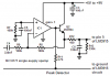
If the high-frequency response is a bit slow in the zero-crossing point because the op-amp goes too negative then I hope adding D1 will keep it under control. If D1 don't help then it ain't going to be there.
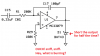
R25 is there to protect the op-amp when power is turned off, there is potentially a lot of juice in that big 33uF. Otherwise, the 2nd stage is just a buffer/follower.
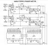
I want this to be a real slow decay. These indicators are not there to entertain me, they are there to show me how hot a signal I have, so I prefer the lights stay on too long in case I'm looking the other way. I really don't need another VU meter response, I want to set the mic gains to prevent clipping and move on to all the other recording tasks.

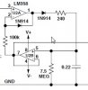
Just for fun, I added a super-peak hold to the top red clip LED. I hope that can keep the 0dB light on for a few seconds longer. I don't really know if the '33078 can dump that much charge into it the cap. I really don't need a precision rectifier in there as the peak voltage will be about 12 volts. I'll experiment to see how long the clip LED stays on. Again, if it don't work, it's outta there.
 
Thanks. I'll see if I can figure that out.

EDIT TO ADD: Didn't work but the drag and drop thing did.
Hmm that's odd. As well as drag and drop, you can use copy image ad paste into your ETO posting window.
spec
 
Last edited:
I have a few LM3915 modules built by National Semiconductor a long time ago. They use a Blob-On-Board IC and an LED module with 10 dim red LEDs in it.
 
I think bounty hunter wins the contest for economical. Looks like a pretty clever design. Since I already have dual supplies and voltage references distributed across the whole system, those wouldn't cost me anything per channel.
I would want to upgrade the '358s though for faster response.
 
The emitter-base reverse voltage of the transistor will exceed its maximum allowed voltage of 6V for half the time or more which will slowly destroy it by avalanche breakdown. My circuit has a lower voltage single supply so the problem does not occur.
I do not like to see the output of U1 shorted by D1 for half the time.
 

Attachments

  • shorted output.png
    shorted output.png
    24.8 KB · Views: 143
Hmmm. That would be a problem.
I'm not too concerned about the op-amp because it is current limited, but if I remove the diode then the transistor gets cooked, and it might anyway.
Maybe if I put the transistor in a socket and keep a steady supply of them available it would work?

..well at least I have a long weekend to keep thinking about it.
 
You can do it cheaper. I built a bar graph design back in about 1976 before the bar graph display chips existed and each 8 segment display was built up using a pair of cheap LM339 comparators and resistor dividers to set each inputs voltage point, you also need a reference voltage. Lots of parts, lots of hassle but it can be done. That antique is still running.....
One thing to watch with the LMx39 comparators is the low sink current: worst case 6mA, although you can generally squeeze around 10mA out of most of them. So long as 6mA LED forward current would give sufficient brightness that would not be a problem.
spec
 
Last edited:
Just a bit more meat for the pot. You can make a simple fast and well behaved peak detector with a comparator. Here is a couple of examples from the LMx11 data sheet. The 1M resistors provide the restore constant current.

I did an outline design and, for audio work, it looks like you could do the job with an LM139 family comparator with a small holding capacitor to cater for the LM139s low output current capability. Just thinking out loud really though.
spec

2016_03_24_Iss01_LM311_PEAK_DETECTOR.png
DATA SHEETS
(1) LMx11 Comparator
https://www.ti.com/lit/ds/symlink/lm111.pdf
 
Last edited:
Status
Not open for further replies.

Latest threads

New Articles From Microcontroller Tips

Back
Top