Electro Tech is an online community (with over 170,000 members) who enjoy talking about and building electronic circuits, projects and gadgets. To participate you need to register. Registration is free. Click here to register now.
Welcome to our site! Electro Tech is an online community (with over 170,000 members) who enjoy talking about and building electronic circuits, projects and gadgets. To participate you need to register. Registration is free. Click here to register now.
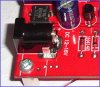
Looking at that picture closely, I see what appears to be a full-wave bridge rectifier just above the power connector at the bottom left of the board so you should be able to power the board with an AC or DC power 'brick' or 'wall wart' power supply...
It looks like there's a 78L12 regulator in a TO92 package with two diodes below it for developing approximately 13.2v for VPP and that will be the highest voltage on the board... Add 3 volts to that for a total of approximately 16.2vdc at the input of the 78L12 regulator...
An AC power 'brick' with a 13-16vac 100ma rating or a DC power 'brick' with a 16-19vdc 100ma rating should work fine... But you won't know if the Power Jack is 2.1 or 2.5mm type until you get the board...
Have you tried asking the Proprietor? I exchanged emails with him about a month ago when I had a question...
In addition to what Mike said, I would add that because the smoothing capacitor is so tiny, you are better off using only DC for the board. In fact, the voltage range is already printed on the circuit board.
Then the full-wave bridge rectifier must have been included in the design to allow for "any polarity" on the power plug... Good idea...
Unfortunately, the full-wave bridge will drop approximately 1.0vdc and you'll still need approximately 13.2v for VPP at the output of the regulator plus the regulator voltage drop (50mv for an LDO type or 3.0v for standard type) plus the full-wave bridge voltage drop... So it seems to me that he's still going to need 14.5 to 17.4 vdc...
Perhaps the designer normally sells one of those loosely regulated 12vdc power bricks that actually puts out something like 15vdc without a load or under light load... This type of 12vdc power supply should work fine...
Yes, I noticed the 12V too. I think the board could be using a voltage triplier with the MAX chip to generate the 13V but I can not tell from the board image. This is a similar design I saw on the net the other day.
But the 12V DC brick (which gives +16V output unloaded) is definitely more likely to be the true reason in this case.
We simply don't know because there are so many ICD2 clone products with different design. And far too many DC bricks(unregulated) give out higher voltage with no load.
The 100% sure way is to ask the seller whether it will work with a 12V battery.
When you finally decides to buy the ICD2 from this site, make sure yours comes in an enclosure/case and not just the board. As they advertised clearly that "it is totally enclosed".
I also found the following photo from the same site difficult to understand.
Edited: photo removed as I have made a mistake. The photo is OK.
I don't see the problem?, a 40 pin Aries ZIF socket is the standard socket used on many PIC programmers - you fit 8 pin, 14 pin, 18 pin, and 28 pin at specific places in the socket (40 pin of course fills the socket).
Check the P16PRO40 circuit, as far as I'm aware it was the first to use this particular method? - hence it's use of two Vpp lines, the normal one Vpp and an extra one called Vpp40 - which is used for 40 and 28 pin devices.
It's all down to clever wiring, so you can switch any of the chips to programming mode, without sticking Vpp where you shouldn't.
I made a mistake as I cannot understand how a 8-pin device can be connected to the 40-pin socket pins. Now I look closely and see the long contacts for the pins along the edge of each slot. At a distant, it appears that the socket has contacts for 40-pin device only.
I made a mistake as I cannot under how a 8-pin device can be connected to the socket pins. Now I look closely and see the long contacts for the pins at the edge of each slot. At a distant, it appears that the socket has contacts for 40-pin device only.
I know I am going a long way with this power supply question, but I heard some stories where a guy burnt out his board because he used a wrong power supply.
Ok, the guy said it requires 800mA~1.5A 12~16V. Isn't a typical laptop power supply have this parameter?
If you are supplying +5V to your project using the +5V from ICD2 then you'll need a power supply of 12V 800mA to power up both your circuit and the PIC, assuming your project does not requires more than 800mA. If you use higher supply voltages, then the 5V regulator on the ICD2 circuit board will get very hot and eventually overheated. So if your project draw a lot of current, keep the input voltage as low as possible.
If you just want to program the PIC chip alone, or your project is powered using yet another supply, then any power supply with 12-16V output is fine as PIC needs only a few mA just for programming.
Typical laptop power supply can be used if the voltage output is within 12-16V.
So, basically, the 5V regulator heats up if a high voltage ABOVE 12V with LOTS of current? Power disspation = current x voltage? (Sorry that I sound very noobish
Thanks for all your help. I will keep posting if I have more questions.
Oh, one more thing. If a power supply is rated at 12V 600mA, then it means it puts out 12V constantly and can put out UP TO 600mA? So, the application can use UP TO 600mA? What happens if I use significantly more than 600mA or less than 600mA?
Oh, one more thing. If a power supply is rated at 12V 600mA, then it means it puts out 12V constantly and can put out UP TO 600mA? So, the application can use UP TO 600mA? What happens if I use significantly more than 600mA or less than 600mA?
Power supply comes in two categories. Regulated and non-regulated. For the first type, the word "Regulated" would usually be marked on the supply as they sell for a higher price. If you don't see the word, never assume it is of the type regulated.
Non-regulated power supply does not have means to control its output voltage when the external loading changes. In most cases they are just low voltage transformer secondary fitted with rectifying diodes and smoothing capacitors. They will provide the marked current at the marked voltage. This is fine if one always use the marked current. But if less currrent is used, the output voltage will rise. A 12V unregulated power supply can output up to 17V or more when measured using a voltmeter under no load condition.
For a regulated power supply, the output voltage is controlled by an electronic device such that it will maintain its output voltage at a fixed level, for any loading up to the marked rating.
When the loading exceed the rating, the output voltage of all supplies will usually drop or the supply simply shuts down depends on the design.
However, some large switching regulated power supply, if designed for a constant load, require certain amount of output loading to function properly. Some other switching supplies, on the other hand, can provide a fixed voltage without shutting down. Most regulated power supplies on sale in shops can work at zero loading.
Oh, one more thing. If a power supply is rated at 12V 600mA, then it means it puts out 12V constantly and can put out UP TO 600mA? So, the application can use UP TO 600mA? What happens if I use significantly more than 600mA or less than 600mA?
If you use less then 600mA there's no problem, the supply CAN handle 600mA, less doesn't hurt...
If you use more then it depends on the supply.
If it has a current limiter it'll limit the current at it's maximum (to protect itself), Output voltage will drop...
if it doesnt have a current limiter then the overload can damage the supply. The supply will probably have a fuse that blows but damage may already be done ...
Could be that there isnt a fuse in it :? ...
The transfo will supply much more current then it's rated for when shorted (obviously overloading it, with a significant drop in output voltage)...
While it will survive that for a short time, don't do that for extended periods.
You should also consider adding a current limiter for the safety of your project. When you make an error in your test setup, and use a supply wich can deliver up to 8A - Parts might/will get damaged...
If you use a current limiter set to very low current, you can test new circuits relatively safe ...
To me, it seems that 12VDC 1000mA unregulated power supply should work fine for powering ICD2, since the voltage range is 12V~16VDC and current requirement is 800mA to 1.5A, although I am a litle concerned that if indeed ICD2 uses 1.5A continuously for a long time, my wallwart may blow up.
This site uses cookies to help personalise content, tailor your experience and to keep you logged in if you register.
By continuing to use this site, you are consenting to our use of cookies.

")