Continue to Site

Welcome to our site!

Electro Tech is an online community (with over 170,000 members) who enjoy talking about and building electronic circuits, projects and gadgets. To participate you need to register. Registration is free. Click here to register now.

  • Welcome to our site! Electro Tech is an online community (with over 170,000 members) who enjoy talking about and building electronic circuits, projects and gadgets. To participate you need to register. Registration is free. Click here to register now.

Power stage for stepper motor using IRF9520 and ULN2803

Status
Not open for further replies.

AlainB

Member
Hi,

I would like to add a bigger power stage to some of my stepper drivers that use ULN2803 as power driver for unipolar motors. Those drivers provide the logic feeding the ULN2803 with the full step sequence needed to run a small motor.

I have about 50 IRF9520 PNP Mosfets doing nothing so I would like to use a few of them for that purpose.

https://www.uib.es/depart/dfs/GTE/education/industrial/tec_analogiques/IRF9520.pdf

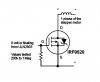
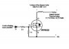
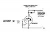
I already tested the schematic below on a breadBoard and it is working. How good, I can't say.

I am not familiar with PNP Mosfets but as I undrestand it, The ULN2803 will provide the Gate of the Mosfet with 0 volt (ground) or will be floating. With 0 volt, the mosfet will switch on. The resistor betwen gate and source is there to switch the mosfet off when 0 volt (ground) is not present. Leaving the gate floating is not possible.

Please correct me if I am not right about what I said above.

With these mosfets, I would like to drive an unipolar motor not exceding 2A per phase and at a maximum of 2 kHz, I mean that each mosfets would switch on and off a maximum of 2000 times per seconds (1 kHz would be fine too).

Is this design acceptable? If so, what would be the optimal value for the gate-source resistor?

Will the mosfet run fully on and fully off?

Would there be another way to achieve what I am looking for, using those mosfets?

Any help is quite welcome!

Thanks!

Alain

irf920-power-stage-jpg.32453
 

Attachments

  • IRF920 Power stage.jpg
    IRF920 Power stage.jpg
    19.8 KB · Views: 3,984
Last edited:
That should work fine with the ULN2003 driving the FET gates, but don't exceed the VGS limit for the FET, which means the PSU can't be above (say) 15v.

At 2kHz you dont have to switch the FETs that fast, so 1k gate pull-up resistors will probably be ok.

Also you probably won't get a unipolar motor to go as fast as 2kHz, especially with a 15v supply. It may only get about 5 RPS (1kHz).

And obviously you will need to conenct the common wire of the unipolar stepper to ground, not to +.
 
I hate MosFets!!!

Every time I try to use them Murfy is comming and something is blowing or making smoke. Already 2 ULN2803 plus the logic of one of my controller that I still have to investigate. This time I don't blow the mosfet itself like before. No I blow just about everything else! I am lucky that my parallel port is still working.

Well, all this is my fault anyway!

For now I have questions about PNP Mosfets for steppers or anything else in fact.

Can we say that as soon as the gate is hit with 0 volt (ground), the fet will switch fully on?

How to be sure to turn it completely off? In my tests I was using the 30 volts supply as Vgs. The max should be 20 volts but 30 volts didn't kill it. I did try a 1k resistor but is was getting hot. I tried fron 200K to 1 Meg and they seem to work nicely. But still I am not sure that the fet is off completely.

At what voltage should I hit the gate and how to do that with a 30 volts supply? Or simply, how would you turn them off?

Alain
 
Last edited:
With a 30V supply you should still have 1k from gate to source (+30V). But you should have 2k (or 2.2k) from the 2803 to the gate. The divider of 2k and 1k will divide the 30V down to 30*(1k/(1k+2k))=10V.
 
I don't get it!

As I understand it, the output of the ULN2803 will be a) 0 volt (ground), in that case the mosfet will turn on or b) it will be floating (not giving any voltage) and, if so, I don't see what the 2K resistor of the divider will do to help turn the mosfet off.

I would also be very happy if someone could clarify these previous asked questions for me:

"Can we say that as soon as the gate is hit with 0 volt (ground), the fet will switch fully on?"

and,

"How to be sure to turn it completely off?"

Thanks!

Alain
 
Last edited:
When the gate voltage is equal to the SOURCE it will be fully off. The 1k resistor that I described from gate to source will accomplish this.

For a P-Channel MOSFET, when the the gate is -10V from the source the transistor will be fully on. The divider of the 2k to 0V and the 1k to 30V will accomplish this.
 
Is this drawing Ok?

irf920-power-stage-jpg.32725


What is the reason for using a 1k value for the gate/source resistor?

Alain
 

Attachments

  • IRF920 Power stage.jpg
    IRF920 Power stage.jpg
    28.2 KB · Views: 5,017
The drawing is almost OK. The diode isn't really necessary. In any case, it's backwards.

You should have a diode across the coil and resistor (cathode on drain, anode on ground). The diode should have a current rating of at least 1A and voltage 100V (any 1N4001-1N4007).

The resistor from gate to source is 1k because you chose it, it's sort of OK and I didn't want to confuse you at that point in time. However now that you mention it, it can be a wide range of values.

First I mention that in this circuit, the approximate ratio of the two resistors is important. If they are 1k and 2k ohms, the MOSFET switches pretty fast (gate C is 350pF so it's about 1/3 microsecond) and the resistors consume a few milliwatts. The resistors can be 220k and 470k ohms, in which case the MOSFET would take 220 times as long to switch and the resistors consume almost nothing. Going the other way, if you chose 220 and 470 ohms, you would need large (1 and 2 watt) resistors, they would get very hot but the MOSFET would switch 4 times faster.

If I were driving a stepper at 3kHz (period 333 microseconds), I would tend to design for less than 2 microsecond switching speed, or resistor values of 2200 and 4700 ohms.

Why this switching speed? The load is about 40 watts. In the transition of switching, the transistor is seeing (up to) one quarter of that, or 10. If I keep the switching time to 1.2% (4/333; remember two edges per cycle) of the time, the switching losses (heat) is less than 10*1.2%, or an average of less than 120 milliwatts. These are very approximate. You can do detailed math if you're less lazy than I.

The static power in the transistor is (1,4A*1,4A*0,48Ω)=0,95 watt. Assuming 50% duty cycle, that's another 0.48 watt in the IRF9530. Since 0.48Ω is guaranteed, we don't need a safety margin.

Total power dissipation in your transistor when the motor is turning (with these assumptions) 6/10 watt. Without a heat sink, the transistor temperature (62 degrees C/W) will rise 37C, and will be 62-67 degrees C. OK for the transistor, but slightly uncomfortable. :rolleyes:

If you stop the motor with one or more coils "on" continuously, the transistor, motor, and resistor will be very hot.
 
Thank you for your very elaborate reply!

Was your reference to an IRF9530 a typo? if not, does it change something?

My idea of putting a diode at the gate was to prevent the ULN2803 to receive any positive voltage that could destroy it. I changed the orientation but will not put it if it is not needed.

I would like the mosfet to be able to switch for a theorical motor speed of 1000 rpm. It is probably not possible to get it from such a simple driver. 300 to 500 is what I expect and more 300 than 500 if I want an usable torque. 1000 rpm is 16,66 revolutions per second and the motor has 200 steps per revolution so 3333,3 steps per second for that theorical speed. There is 4 mosfets per driver so each mosfet has to switch on and off 833 times per second, half that for my expectations. I drive the motor full step, that is 2 coils always energized at the same time, if it change something.

I am sure there is no problem there for the mosfets but how about the diodes suggested betwen drain and ground. Are they fast enough? How about using a fast diode? If needed, which one to use?

Thanks again!

Alain

irf920-power-stage-jpg.32761
 

Attachments

  • IRF920 Power stage.jpg
    IRF920 Power stage.jpg
    31 KB · Views: 3,323
Last edited:
That schematic looks like it escaped from the twilight zone. :)

1. The unipolar motor 5.2v 1.4A wont do 17 RPS. Not with any shaft power. Figure 5 to 8 RPS max and even that will be tricky with a resistive driver. With a good microstep driver you might get 17 RPS.

2. 17,774 ohms? I assume thats 17.774? You have to run 2-phase on to get ANY speed out of that stepper, so you always have 2 coils on. So you need a resistor to pass 24v at 2.8 amps or about 8.6 ohms.

3. You don't need any diodes, so can lose both the diodes. The ULN chip does not require a diode, and that diode across the stepper coil will cause "slow decay" current mode which is the worst thing you need trying to make that old stepper run fast. The FET internal diode will take care of the motor recirculating current.

4. Have you considered just buying one of these kits;

it is a smoothed microstepping driver that will do 1.4 A and is specifically designed to get the best speeds and performance etc from old unipolar motors like your 5v 1.4A motor. You can probably even drop it to 1A /phase and use a lot less than 30v. The kit is not that expensive by the time you factor in all your time to make this design above that just wont work very well.
 
You assumed right but I don't understand wy you have to assume that anyway. Unless this is a "French thing" only. To me, the decimal separation can be a point or it can be a comma. My Excel for instance can't do any calculation if the decimal separation is not a comma.

Yes a 8,6 Ohms would do but at near 70 watts. In the "twilight zone" schematic I am just showing one phase of the motor. Two 17,7 Ohms would be needed for the complete motor and could be a better choice in my humble opinion. (I am talking of a 6 or 8 wires stepper motor here. A 5 wires motor would require a single big resistor or 4 smaller ones.)

For the RPM, as I explain in my previous post 300 rpm (or 5 rps) is about what I expect for an usable torque. I made a few drivers up to now and that is more or less the speed that I get.

Here is one of my driver in action (using TIP121 Transistors). Sorry if you already saw it. I is not the first time that I post this link:

https://www.youtube.com/watch?v=OwjynFhSbWk

I am not looking for a commercial driver. As I said in my first post, I have a bunch of PNP mosfets that I would like to use and hopefully by the same time learn how to make them work properly.

Thanks

Alain

Edited:

(From Wikipedia and edited)

Countries using numerals with decimal point:

Australia, Brunei, Botswana, Canada (English-speaking), Hong Kong, India, Ireland, Israel, Japan, Kenya, Korea (both North and South), Malaysia, Mexico, New Zealand, Nigeria, Pakistan, People's Republic of China, Philippines, Singapore, Sri Lanka, Switzerland, Taiwan, Tanzania, Thailand, Uganda, United Kingdom, United States (including insular areas), Zimbabwe.

Countries using numerals with decimal comma:

Albania, Andorra, Argentina, Armenia, Austria, Azerbaijan, Belarus, Belgium, Bolivia, Bosnia and Herzegovina, Brazil, Bulgaria, Cameroon, Canada (French-speaking), Costa Rica, Croatia (comma used officially, but both forms are in use elsewhere), Chile, Colombia, Cuba, Cyprus, Czech Republic, Denmark, Dominican Republic, Ecuador, El Salvador, Estonia, Faroes, Finland, France, Germany, Greece, Greenland, Guatemala, Honduras, Hungary, Indonesia, Iceland, Italy, Kazakhstan, Latvia, Lithuania, Luxembourg (uses both separators officially), Macau (in Portuguese text), Macedonia, Moldova, Netherlands, Norway, Nicaragua, Panama, Peru, Paraguay, Poland, Portugal, Romania, Russia, Serbia, Slovakia, South Africa (officially, but dot point is commonly used in business), Slovenia, Spain, Sweden, Turkey, Ukraine, Uruguay, Venezuela, Vietnam.
 
Last edited:
Understandable and clear basic informations on how PNP mosfets works is not easy to find on the net. I wish that a gifted person, knowing what he is talking about and speaking slowly, would write something like "PNP mosfets 101" assuming that his eventual readers would not be engineers.

For instance, something not clear about the negative voltage. We see often references to negative voltage when reading about PNP. " -10 volts to the gate will turn the mosfet fully on". I would be encline to think that a negative voltage is a voltage below 0 volt. Minus 10 volts is a negative voltage. But if I understand well some previous explainations from mneary, it is not really that:

" For a P-Channel MOSFET, when the the gate is -10V from the source the transistor will be fully on. "

Then, if the source is 30 volts, it is still a positive voltage that is applied to the gate.

Pretty confusing!!:)


Alain
 
Last edited:
2N9530 was a typo. [edit: 2N9530 was yet another typo; I meant IRF9530 was a typo, your part is IRF9520]. A cat is on my lap between me and the keyboard sometimes [edit: often?] I don't proofread thoroughly.

I agree 17 rps is beyond what you can expect from this motor on a resistive driver. I didn't notice earlier that's what you need/want.

The diode isn't needed if you drive directly from the ULN3808, but with the P-MOSFET buffer, you do need to protect the MOSFET. By the way, the diode terminal on the ULN3808 must be left open or hooked to 30V through a resistor. (Please check its voltage rating).

The diode should be connected between the drain and GROUND to improve the decay characteristics.

You have noticed the incredible power dissipation (35W) in those 18 ohm resistors?

p.s. I hope I haven't confused anyone by carelessly using both the comma (,) and the dot (.). I'll use the dot exclusively since I'm in the USA.
 
Last edited:
I apologise AlainB for nitpicking on the decimal point. My post did sound insulting although it was not my intention to insult you or your culture. My understanding was that this is an English language only forum, and the correct English language symbol for a decimal point is a decimal point which is the reason i nitpicked.

...
The diode isn't needed if you drive directly from the ULN3808, but with the P-MOSFET buffer, you do need to protect the MOSFET.
...

Incorrect. The FET internal body diode provides all the necessary protection in this stepper circuit.


...
The diode should be connected between the drain and GROUND to improve the decay characteristics.
...

Also incorrect, putting the diode from stepper coil to ground int his circuit puts the motor recirculating current in slow decay mode, this severely restricts the higher speeds of the motor which is what the OP requires.

The correct place to add the diode for high motor speed use is in fast decay mode which is to put the diode in parallel with the FET, and that is not necessary as the FET already has a diode there.
 
I was not insulted. Depending on the software, I have to use sometimes the comma and sometimes the point. But when I am writing, if I don't think specially about it, I will use the comma.

Thank you both for your reply. I really appreciate it.

I am not looking for a way to improve the speed of the driver. What I am really seeking is a clear understanding on how PNP mosfets works. How to have them fully on and fully off, the switching speed calculations and the use of resistors for that matter and what else. But maybe I was not clear enough about that. Some of my questions remain unanswered so maybe I will start a new thread, " PNP Mosfets 101 ", without mentionning anything about steppers motors, to try to get only to the basic of the mosfet.

Thanks!

Alain

(In a few of my drivers using TIP121, a darlington with built in diode, I do not use protective diodes. Those drivers are all working fine. So maybe diodes are not required.)
 
Last edited:
IThe FET internal body diode provides all the necessary protection in this stepper circuit.
The FET internal body diode, as a classic diode, isn't in the correct place.

It's true that the body diode in the IRF9520 can absorb substantial energy in avalanche. However, according to my calculations, in this application the power to be absorbed is much more than [edit] we can reasonably dispose of in the transistor. [/edit]
Also incorrect, putting the diode from stepper coil to ground int his circuit puts the motor recirculating current in slow decay mode, this severely restricts the higher speeds of the motor which is what the OP requires.
Directly across the coil is the slow decay mode; the faster decay occurs with a resistance in series with the diode. Classically we put the resistor (or a zener) directly in series with the diode for fastest decay, but in this circuit we already have a resistor to re-use. It's the same resistor we used to decrease the time constant of the current attack time.

The placement of the positive rail at the bottom is extremely confusing; redrawing the circuit with 0V at the bottom was helpful to me.
 
Last edited:
It would be nice if you could share your new drawing with the way you think the circuit should be designed.

Alain
 
Last edited:
The FET internal body diode, as a classic diode, isn't in the correct place.

There's no point us having a circular argument. Read "Jones on steppers" which is where I got most of my stepper knowlege from when I was designing the linistepper project. Then you can argue with THE expert instead of arguing with me because I'm done with it. :)

Slow decay modes keep the motor recirculating current within the winding with or without a series resistor, this keeps the magnetic field within the coil continuing for as long as possible. Fast decay modes feed the coil back-emf back to the PSU, usually via diodes from the coil to the PSU + rail (like the FET body diode). This allows the magnetic field in the coil to collapse quite quickly and allows higher motor speeds.
 
Jones has an excellent tutorial. I think his illustrations are helpful.

See figure 3.2 (left schematic) The diode is that which I call the "classic" recirculating diode. Its decay mode is slow; I think we agree.

See figure 4.1 (left schematic) R2 is the resistance in series with this "classic" diode which accelerates the decay in a unipolar winding. [edit] Figure 4.7 illustrates the function of R2 to speed up multiple unipolar windings. The paragraph which follows describes the trade off between efficiency and speed. [\edit]

[edit - delete this sentence ] The body diode is shown across the switch element. It is required if a unipolar winding has an opposing winding (as most do). [\edit]

@Alain: It's after 1 am right now; I'll try to draw a proper diagram in the morning.
 
Last edited:
It would be nice if you could share your new drawing with the way you think the circuit should be designed.

Alain
Alain,
I apologize for taking so long, especially since the edit of your own diagram was so simple. Here it is.

Note that your diagram only shows one winding. If you've had the time, you would have read section 4 of the Jones stepper articles.

Also, I should highlight that, as Jones mentions, resistive current limiting isn't an efficient method; it was more popular in the 80's than it is now. When I had to deliver an efficient driver in the early 1990's, resistive limiting was out of the question. Even diode losses were unacceptable, so we had to invent our own configuration. (US Patent 5,744,922) Unfortunately it's for a bipolar stepper which doesn't use the parts that you have on hand.
 

Attachments

  • IRF920 Power stage.jpg
    IRF920 Power stage.jpg
    27 KB · Views: 1,507
Status
Not open for further replies.

Latest threads

New Articles From Microcontroller Tips

Back
Top