mading2018
Member
Hello,
I have some concern regarding an equation for calculating power losses for half - and full diode-bridge.
Can someone please check if this equation is correct or not? See the attached image.
"

Fig. 1. Typical diode full-wave bridge.
Full-wave diode bridges are found in many electronic systems (Fig. 1). At typical AC power line voltages, the drop across the diodes has little impact on the rectified output voltage and diode power dissipation. However, diodes in low voltage, high power rectification applications dissipate significant power and the inherent diode drops take a significant bite out of the operating voltage. For example, power dissipation of the diode bridge in Fig. 1 is:
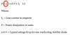
Equation: P = 2 × 0.6 V × IL (1)
Where:
IL = Line current in amperes
P = Power dissipation in watts
0.6 V = Typical voltage drop for one conducting rectifier diode"
What I understand from this equation, this gives total power losses for a whole bridge, by multiplying with 2.
If I had multiplying with 1, I would obtain half of the power losses (which would be for a half-diode bridge).
I really need a confirmation of this soon...
Ref:
https://www.powerelectronics.com/pm...er-cuts-power-dissipation-improves-efficiency
I have some concern regarding an equation for calculating power losses for half - and full diode-bridge.
Can someone please check if this equation is correct or not? See the attached image.
"
Fig. 1. Typical diode full-wave bridge.
Full-wave diode bridges are found in many electronic systems (Fig. 1). At typical AC power line voltages, the drop across the diodes has little impact on the rectified output voltage and diode power dissipation. However, diodes in low voltage, high power rectification applications dissipate significant power and the inherent diode drops take a significant bite out of the operating voltage. For example, power dissipation of the diode bridge in Fig. 1 is:
Equation: P = 2 × 0.6 V × IL (1)
Where:
IL = Line current in amperes
P = Power dissipation in watts
0.6 V = Typical voltage drop for one conducting rectifier diode"
What I understand from this equation, this gives total power losses for a whole bridge, by multiplying with 2.
If I had multiplying with 1, I would obtain half of the power losses (which would be for a half-diode bridge).
I really need a confirmation of this soon...
Ref:
https://www.powerelectronics.com/pm...er-cuts-power-dissipation-improves-efficiency
Attachments
Last edited:
") .
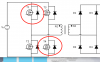
. But if only look at the conduction losses, which is this equation for power losses for one MOSFET: