Continue to Site

Welcome to our site!

Electro Tech is an online community (with over 170,000 members) who enjoy talking about and building electronic circuits, projects and gadgets. To participate you need to register. Registration is free. Click here to register now.

  • Welcome to our site! Electro Tech is an online community (with over 170,000 members) who enjoy talking about and building electronic circuits, projects and gadgets. To participate you need to register. Registration is free. Click here to register now.

Power loss calculation question

Status
Not open for further replies.

Stenberg

New Member
Hi!
I have gotten a little stuck, and need to find an answer before being able to continuing with calculations.

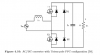
A have a AC/DC converter Totem-pole, a picture is uploaded below.
I have calculated power losses for a diode and for a transistor.

My question is, since the transistors are placed in a half-bridge, and conducting one at a time, are the calculated power loss for one transistor the power loss for one or both transistors in the half-bridge?

I have added the calculations below, please take a look.

Thanks for your help!

//Stenberg
 

Attachments

  • Calculation.PNG
    Calculation.PNG
    609.7 KB · Views: 111
  • Totem.png
    Totem.png
    13.9 KB · Views: 96
Hello,

Cant read your writing as it is too light. Dont you check before posting?

A transistor draws current when it is on but not much when off, so the power dissipation is mostly when on.
There are also switching losses that would have to be added if there is significant switching times.
 
Hi, I am sorry.
I have now added new pictures written in better text. Hopefully they are clearer.

Thanks.
 

Attachments

  • Pic2.PNG
    Pic2.PNG
    1,008.6 KB · Views: 92
  • Pic1.PNG
    Pic1.PNG
    1 MB · Views: 97
Hello,

Are you aware that for the switching times the voltage is falling when the current is rising, or the voltage is rising when the current is falling, so there is a factor of 1/6 involved for that portion of the cycle as an approximation.

Also, one of the schematics does not look right with an inductor running into the gate of one of the MOSFETs.
 
Status
Not open for further replies.

Latest threads

New Articles From Microcontroller Tips

Back
Top