Continue to Site

Welcome to our site!

Electro Tech is an online community (with over 170,000 members) who enjoy talking about and building electronic circuits, projects and gadgets. To participate you need to register. Registration is free. Click here to register now.

  • Welcome to our site! Electro Tech is an online community (with over 170,000 members) who enjoy talking about and building electronic circuits, projects and gadgets. To participate you need to register. Registration is free. Click here to register now.

power analysis concepts etc.

Status
Not open for further replies.
So the formulae seem to be okay but one thing surprises me that why they are not mentioned anywhere. I tried to search them everywhere but couldn't find. They were just made up...?

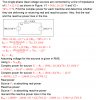
I proved it for Z=R+jX although my head started spinning after seeing all that math and formulas again! Please see here.

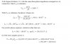
I believe that the purpose of the formulae, at least the case α=β=2, is to be able to find the power for any other voltage_rms value other than nominal or rated voltage_rms value in a rather straightforward manner.

Does α=β=0 signify the case of constant power?

I'll try to prove α=β=1 case later today. Thank you.

Helpful links:
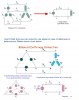
Types of loads: constant current, constant power, constant impedance, constant voltage
1: https://electronics.stackexchange.c...t-constant-power-and-constant-impedance-loads
2: **broken link removed**
3: https://books.google.com/books?id=lQPeDAAAQBAJ&pg=PA3&dq="constant+voltage+load"&hl=en&sa=X&ved=0ahUKEwiLq4GRwpnWAhVO22MKHarkCiQQ6AEIKDAA#v=onepage&q&f=false

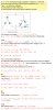
First of all, (R+jX)(R-jX)=R^2 + X^2, not R^2 - X^2. Second of all, power dissipated across impedances in series is proportional to the voltage across each impedance, not the square of the voltage. For instance, for a 1 ohm and a 2 ohm resistor connected in series to a 3 volt source, the 2 ohm resistor will drop twice the voltage as the 1 ohm resistor and dissipate twice the power.

Ratch
 
Thank you.


I had already corrected the mistake but forgot to fix it here.


I was able to found the formulae in few online books. I could put the formulae in proper context now and at the same I have few questions. I'll do it today.


It wasn't me. It was the instructor. By the way, I couldn't even understand his approach to solve the case α=β=2. Please see the attachment. Thank you.

Are you trying to derive the formula in the attachment?
 
Hi Ratch,

Thank you for trying to help me. That problem you were trying to address has already been solved. Soon, I'll write down the solution in complete and share here.

If possible, you could help me with the problem in post #19. Thanks.
 
Hi,

Please have a look here.

The phase angle for current I21 is -127° . I cannot know if it's leading or lagging because this calculation was done with reference to voltage source V2 which has phase angle of 0 degree. I understand that it could be said V2 could be thought of as 585∠-180° and in this way current would lag the voltage. But I don't see the logical reason for proceeding like this. Could you please guide me? Thank you.

Who cares what the phase angles are? Just do the complex arithmetic and they should take care of themselves. The attachment shows the values of V1, V2 ,Z, and calculated current I. Now we can find the power of V1, Z, and V2 as shown. Notice the conjugate of the current is used. Do you know why? Then, as a check, we use Tellegen's theorem to check that the power output is equal to the power input plus the power dissipated. V1 outputs real and absorbs reactive power, the line absorbs both real and reactive power, of course, and V2 absorbs real and outputs reactive power. All the powers should add up to zero. Be sure to ask if you have any questions.

PG1995.JPG


Ratch
 
Thank you, Ratch.

Actually I was already able to solve this problem but was stuck at a conceptual point which was stated in post #19. Here is the full solution. So, let me repeat the point which is confusing me.

The phase angle for current I21 is -127° . I cannot know if it's leading or lagging because this calculation was done with reference to voltage source V2 which has phase angle of 0 degree. I understand that V2 could be thought of as 585∠-180° and in this way current would lag the voltage. But I don't see the logical reason for doing this and proceeding like this.

Thank you.
 

Attachments

  • 2.8chap2.jpg
    2.8chap2.jpg
    248 KB · Views: 620
Hi,

Please have a look here.

The phase angle for current I21 is -127° . I cannot know if it's leading or lagging because this calculation was done with reference to voltage source V2 which has phase angle of 0 degree. I understand that it could be said V2 could be thought of as 585∠-180° and in this way current would lag the voltage. But I don't see the logical reason for proceeding like this. Could you please guide me? Thank you.

If current is leading the voltage by 359°, it could also be said that it is lagging the voltage by 1°. Plus or minus, lagging or leading, is determined by whether the angle is <= 180°. In the case of I21, the current angle is -127° from V2 and is lagging the V2 voltage by 127°.

Ratch
 
Thank you.

But isn't the maximum phase angle between the voltage and current supposed to be less than or equal to 90°? If this is correct then saying that current lags the voltage source V2 by 127° doesn't make much sense. Thanks.
 
Thank you.

But isn't the maximum phase angle between the voltage and current supposed to be less than or equal to 90°? If this is correct then saying that current lags the voltage source V2 by 127° doesn't make much sense. Thanks.

A single time constant (STC) circuit with only one voltage source can never support a current-voltage phase difference greater than 90°. That does not mean to say that other circuits with more storage elements cannot allow larger phase differences to exist.

Ratch
 
Thank you.

So, the maximum allowable angle possible to determine leading or lagging is less than or equal to 180°.
 
Thank you.

So, the maximum allowable angle possible to determine leading or lagging is less than or equal to 180°.

Plus or minus angles can be any amount supported by the circuit. But for understandability and standardization, the angles are usually converted and displayed to the equivalent number less than or equal to ±180°.

Ratch
 
Hi

Please have a look here. The answer to part (b) is incorrect. It should be 864 kW, 648 kvar. Anyway, the answer to part (a) is correct. Seemingly, it looks like I didn't make any mistake. Could you please help me to trace out the error in part (b)? Thank you.
 

Attachments

  • 2.12.jpg
    2.12.jpg
    427.5 KB · Views: 628
Hi

Please have a look here. The answer to part (b) is incorrect. It should be 864 kW, 648 kvar. Anyway, the answer to part (a) is correct. Seemingly, it looks like I didn't make any mistake. Could you please help me to trace out the error in part (b)? Thank you.

The attached file is too small and bleary to see adequately.,

Ratch
 
Please click on it, it'll get zoomed in. The resolution is good.

You are right, sorry about the complaint. I have not done any 3-phase probs for over 20 years. I will need a day or so to read up on the technology. Stand by.

Ratch
 
Hi

Please have a look here. The answer to part (b) is incorrect. It should be 864 kW, 648 kvar. Anyway, the answer to part (a) is correct. Seemingly, it looks like I didn't make any mistake. Could you please help me to trace out the error in part (b)? Thank you.

I get the same answer of 424.252 kw. I believe that the calculated value of Vp is wrong. In a delta configuration, the phase voltage is the same as the line voltage of 4157 volts, not 2400 volts.

Ratch
 
Thanks.

I was able to fix one error to get correct value for Q.

fixed_reactive-jpg.108433
 

Attachments

  • FIXED_REACTIVE.jpg
    FIXED_REACTIVE.jpg
    38.1 KB · Views: 354
Thanks.

I was able to fix one error to get correct value for Q.

fixed_reactive-jpg.108433

I see I used the angle between phase and line currents and got the wrong answer. I should have used the angle between the line voltage and phase currents which is -36.87° . Using that angle, I get 864 kw real power and -648 kw vars. I believe that agrees with what you get.

Ratch
 
I'm still not able to get correct value for real power P.

Could you please also help me with the following query.

Please check the attachment. I don't think that one can solve for one phase in case of delta load or delta source without really doing the wye conversion first. Am I right? Thanks.
 

Attachments

  • balanced_y_y_to_single_phase.jpg
    balanced_y_y_to_single_phase.jpg
    124.5 KB · Views: 637
I'm still not able to get correct value for real power P.

Could you please also help me with the following query.

Please check the attachment. I don't think that one can solve for one phase in case of delta load or delta source without really doing the wye conversion first. Am I right? Thanks.

Sure you can. The power formulas are the same for either wye or delta. See attachment.

Ratch

PG1995.JPG
 
Surprisingly, I'm not still able to track the error in my calculation where I'm using line voltage and line current.

surprisingly-jpg.108437


On the other hand, I don't see why you are considering phase voltage V_p and line voltage V_l equal. Please see the highlighted part at the top. According to the text phase voltage and line voltage are different in balanced wye-delta connection.

PS: Furthermore, "θ" in cos(θ) is the angle between voltage and current which means it should be cos(0-36.87). Although cos(-a)=cos(a), I just thought that I should mention it here because in case of reactive power, it would cause an error.

Here is the solution to the problem from solution manual.

Thank you.
 

Attachments

  • surprisingly.jpg
    surprisingly.jpg
    35.3 KB · Views: 388
  • solution2.12.jpg
    solution2.12.jpg
    98.3 KB · Views: 599
Last edited:
Status
Not open for further replies.

Latest threads

New Articles From Microcontroller Tips

Back
Top